Designing parts for CNC machining can feel tricky. You might worry if your design will be too complex or expensive to make. This uncertainty can slow down your projects and lead to costly mistakes. But, with the right approach, you can create designs that are both functional and easy to machine.
To design parts for CNC machining effectively, you need to consider material selection, appropriate tolerances, and design features that are CNC-friendly. This includes avoiding very thin walls, deep narrow pockets, and complex internal geometries where possible. Using CAD software to create precise models and thinking about the manufacturing process from the start are key steps for success.
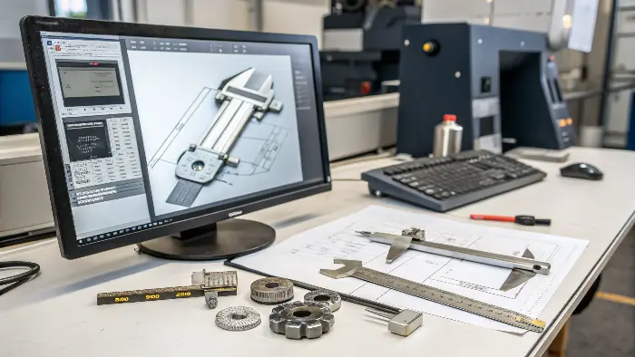
Understanding how to design for CNC machining is a big step. It helps you avoid problems later on. When I first started, I made a few designs that looked great on screen but were a nightmare for the machinists. Learning these principles saved me a lot of time and money. Let’s explore how you can make your CNC design process smoother and more effective.
How to design a machine part for CNC?
Ever had a brilliant idea for a part, but then struggled to make it real for CNC machining? It’s a common hurdle. You want it to work perfectly, but also be easy and affordable to produce. This can feel like a tough balancing act.
Designing a machine part for CNC involves defining its function, selecting the right material, creating a detailed 3D model using CAD software, and applying Design for Manufacturability (DFM) principles. This means thinking about how the part will actually be cut, ensuring features are accessible to cutting tools, and specifying realistic tolerances.
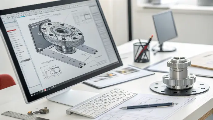
When I design a new part, I always start by thinking about its main job. What does this part need to do? This basic question guides all my other choices. For example, if a part needs to be very strong, that will point me towards certain materials. If it needs to fit into a tight space, that affects its shape and size. I remember one project where we spent ages on a complex design, only to find a simpler shape worked just as well and was much cheaper to make. Thinking about the manufacturing process early on is crucial. You want to design features that standard cutting tools can easily create. This means avoiding things like very deep, narrow slots or internal corners that are too sharp for a tool to make.
Here’s a breakdown of key considerations:
- Function First: Clearly define what the part needs to accomplish. This influences material, shape, and tolerances.
-
Material Selection: The material impacts strength, weight, cost, and machinability. Material Pros Cons Common Uses in CNC Aluminum 6061 Good strength-to-weight, machinable Can be gummy Prototypes, structural parts Stainless 304 Corrosion resistant, strong Harder to machine, more expensive Food grade, medical parts ABS Plastic Easy to machine, affordable Lower strength Enclosures, prototypes PEEK High temp, chemical resistant Expensive, specific machining Aerospace, medical implants - CAD Modeling: Use Computer-Aided Design (CAD) software to create a precise 3D model. Keep designs as simple as possible while meeting functional needs. Use standard hole sizes and radii where you can.
- Design for Manufacturability (DFM):
- Tool Access: Can a cutting tool reach all the surfaces it needs to machine?
- Wall Thickness: Avoid walls that are too thin, as they can vibrate or break during machining.
- Hole Depths: Very deep holes (more than 6 times the diameter) can be challenging.
- Internal Radii: All internal corners will have a radius left by the cutting tool. Design for the largest possible radius.
- Tolerances: Specify only the necessary tight tolerances. Over-tolerancing increases cost.
Thinking through these points helps create a part that is not just functional but also efficient to produce.
What type of software is used to create designs for CNC?
Choosing the right software for CNC design can feel overwhelming. There are so many options, and you might wonder which one is best for your needs. You want a tool that helps you create accurate designs without a steep learning curve.
To create designs for CNC, you primarily use Computer-Aided Design (CAD) software to model the part’s geometry. Then, Computer-Aided Manufacturing (CAM) software is often used to generate the toolpaths and G-code that the CNC machine follows. Some software packages offer integrated CAD/CAM capabilities.
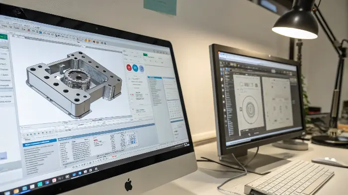
When I first got into CNC, figuring out the software was a big step. It’s like learning a new language. But once you get the hang of it, these tools are incredibly powerful. The main type of software you’ll use to actually draw or model your part is CAD software. Think of it as your digital drawing board, but in 3D. You create the shape, define the dimensions, and make sure everything looks right. After your design is complete in CAD, you often need CAM software. This software takes your 3D model and helps you plan how the CNC machine will actually cut it. It figures out the paths the cutting tools will take, the speeds, and the feeds. Then, it generates the G-code, which is the language the CNC machine understands.
Here’s a closer look at the software involved:
-
Computer-Aided Design (CAD) Software:
- Purpose: Used to create 2D drawings and 3D solid or surface models of the part. This is where you define the exact geometry, dimensions, and features.
- Examples: Autodesk AutoCAD (good for 2D, some 3D), SolidWorks (popular for 3D mechanical design), Autodesk Fusion 360 (cloud-based, integrated CAD/CAM), FreeCAD (open-source).
- My Experience: I started with 2D CAD for simpler profiles, but quickly moved to 3D CAD like SolidWorks and Fusion 360. For complex parts, 3D modeling is essential. It helps you visualize the final product and check for interferences.
-
Computer-Aided Manufacturing (CAM) Software:
- Purpose: Takes the CAD model and allows you to define machining strategies (e.g., roughing, finishing, drilling). It then generates the toolpaths (the route the cutting tool will take) and outputs the G-code that controls the CNC machine.
- Examples: Mastercam, HSMWorks (integrates with SolidWorks), Fusion 360 (has built-in CAM), Edgecam.
- My Experience: Good CAM software is a lifesaver. It automates a lot of the complex calculations needed for toolpaths. Fusion 360’s integrated CAM is great because changes in the CAD model can easily update the CAM setups.
-
Integrated CAD/CAM Software:
- Purpose: Combines design and manufacturing capabilities in a single environment. This streamlines the workflow, as design changes can be quickly reflected in the manufacturing instructions.
- Examples: Autodesk Fusion 360, SolidWorks with CAM add-ins.
Choosing the right software often depends on the complexity of your parts, your budget, and your existing skills. Many offer free trials, so I always suggest trying a few to see what fits your workflow best.
How to write a CNC part program?
Seeing lines of G-code for the first time can be intimidating. It looks like a secret code, and you might think you need to be a computer programmer to understand it. This can make the idea of creating a CNC program seem out of reach.
A CNC part program, usually written in G-code and M-code, provides step-by-step instructions for the CNC machine. While CAM software automates most G-code generation from a CAD model, understanding the basic structure and common codes is very helpful for troubleshooting and making minor edits. Manual programming is rare for complex parts but possible for simple tasks.
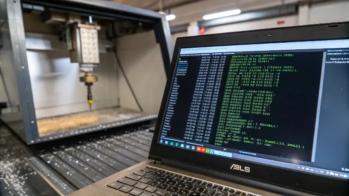
Honestly, when I first looked at a G-code file, my eyes glazed over. It seemed so complex! But the good news is, for most design work, you don’t need to write pages of G-code by hand. That’s what CAM software is for. It takes your beautiful 3D model and translates it into these instructions for the machine. However, knowing a little bit about what that code means can be super useful. It helps you understand what the machine is doing and why. Sometimes, you might even spot a small issue or want to make a quick tweak, and a basic understanding can save you a lot of back-and-forth.
Let’s break down what a CNC program involves:
-
What are G-codes and M-codes?
- G-codes (Preparatory codes): These tell the machine what type of motion to perform. For example, G00 is for rapid movement (getting the tool into position quickly), G01 is for linear interpolation (cutting in a straight line), and G02/G03 are for circular interpolation (cutting arcs).
- M-codes (Miscellaneous codes): These control auxiliary functions of the machine. For example, M03 starts the spindle rotating clockwise, M05 stops the spindle, M08 turns coolant on, and M30 ends the program.
-
Basic Structure of a Program:
A typical CNC program has a logical flow:- Program Start: Often begins with a ‘%’ symbol and a program number (e.g., O0001).
- Safety Block: A series of G-codes to set the machine to a known, safe state (e.g., G21 for metric units, G90 for absolute programming).
- Tool Change: M06 Txx (where Txx is the tool number).
- Spindle On: M03 Sxxxx (where Sxxxx is the spindle speed in RPM).
- Coolant On (if needed): M08.
- Positioning Moves: G00 to move the tool rapidly to a starting point near the workpiece.
- Cutting Moves: G01, G02, G03 with X, Y, Z coordinates and a feed rate (F value).
- Retract and Reposition: G00 to move away from the part.
- Repeat for other operations or tools.
- Spindle Off, Coolant Off, Program End: M05, M09, M30.
-
Role of CAM Software: As mentioned, CAM software is the primary tool for generating these programs for any reasonably complex part. You define the operations in a graphical interface, and the CAM system outputs the G-code.
-
Manual Programming: For very simple tasks, like drilling a few holes or facing a part, some experienced machinists might write short programs directly at the machine controller. But for parts designed in CAD, CAM is the way to go.
Understanding these basics demystifies the process. You don’t need to be an expert G-code programmer as a designer, but knowing what the codes represent helps you communicate better with machinists and understand the manufacturing process.
What are the 7 major parts of a CNC machine?
You might wonder why knowing the parts of a CNC machine matters for design. It seems like the machinist’s job, right? But understanding the machine’s components can actually help you design parts that are easier and more efficient to make.
The 7 major parts of a CNC machine typically include the Machine Control Unit (MCU), bed/table, spindle, tool changer, drive system (motors and ballscrews), input devices, and the cutting tools themselves. Each part plays a critical role in how your designed part is ultimately produced, influencing accuracy, speed, and the types of features that can be machined.
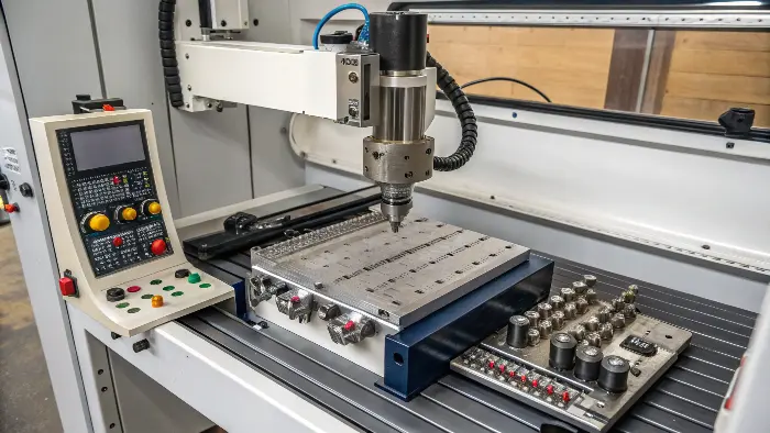
When I started learning about CNC, I focused a lot on the design software. But then I spent some time on the factory floor, watching the machines run. It was a real eye-opener! Seeing how the machine moved, how tools were changed, and how the workpiece was held gave me a much better appreciation for how my designs translated into physical objects. Knowing the machine’s capabilities and limitations can subtly guide your design choices for the better. For example, knowing how a tool changer works might make you think about minimizing the number of different tools needed for your part.
Here’s a look at these key components and their relevance to design:
-
Machine Control Unit (MCU):
- Function: The "brain" of the CNC machine. It reads the G-code program and translates it into electrical signals that control the motors and other components.
- Design Implication: While you don’t directly interact with it as a designer, its processing power and features can affect the complexity of paths it can handle smoothly.
-
Bed/Table:
- Function: The rigid structure that supports the workpiece (often via fixtures or vises).
- Design Implication: The size of the bed limits the maximum size of the part you can machine. The stability of the bed affects the precision achievable.
-
Spindle:
- Function: Holds and rotates the cutting tool at high speeds.
- Design Implication: The spindle’s power and maximum RPM can influence material removal rates and the types of tools/materials that can be used. The spindle nose and tool holder type also dictate tool compatibility.
-
Tool Changer (Automatic Tool Changer – ATC):
- Function: Holds multiple cutting tools and automatically swaps them as instructed by the program.
- Design Implication: Designing parts that can be made with fewer tool changes saves time and money. Consider standard tool sizes.
-
Drive System (Motors & Ballscrews/Linear Guides):
- Function: These are the motors (servo or stepper) and mechanical systems (like ballscrews and linear guides) that move the machine axes (X, Y, Z, and sometimes rotational A, B, C axes) precisely.
- Design Implication: The accuracy and repeatability of the drive system directly impact the tolerances you can achieve on your part.
-
Input Devices:
- Function: How the CNC program is loaded into the machine. This can be a USB port, Ethernet connection, or older methods like floppy disks or RS-232.
- Design Implication: Not a direct design constraint, but part of the overall workflow.
-
Cutting Tools:
- Function: The actual implements (end mills, drills, taps, face mills, etc.) that remove material to shape the part.
- Design Implication: This is hugely important. Your design features must be accessible and formable by standard cutting tools. Avoid internal sharp corners (tools have a radius), very deep and narrow slots, or features that require overly specialized or long tools.
Understanding these components helps you think like a machinist while you’re designing. It bridges the gap between the digital model and the physical reality of making the part.
Conclusion
Designing parts for CNC machining well means thinking about the whole process. From your initial idea to the software you use, and even how the machine works, it all connects. By keeping manufacturing in mind, you can create better, more cost-effective parts. I hope these insights help you on your journey!
