
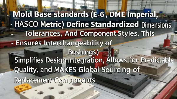
Quick answer: A mold base should be reviewed as the structure that transfers clamp, injection, opening, ejection and handling loads while locating every molding component. Confirm machine fit, plate stack, support, alignment, ejector travel, water and electrical interfaces, access and lifting before steel release. A standard base designation does not prove that the assembled tool is compatible or maintainable.
Release Decision Matrix
| Interface | Review evidence | Risk if missed |
|---|---|---|
| Machine/platen | Envelope, tie bars, locating ring, clamp slots and nozzle | Tool cannot mount, center or seal |
| Structural stack | Plate thickness, support, cavity pressure path and deflection review | Flash, mismatch, wear or dimensional drift |
| Guidance/ejection | Leader, interlock, return, stroke and collision sequence | Damage, galling or incomplete release |
| Utilities/service | Circuit, connector, access, lifting and replaceable component plan | Unsafe setup or prolonged downtime |
Approval Checklist
- Approve primary and backup machine interface data.
- Overlay tie bars, platens, clamps, nozzle, ejector and robot access.
- Review cavity-pressure and clamp-force load paths.
- Check alignment, interlock engagement and wear strategy.
- Simulate full opening, ejection, return and side-action sequence.
- Map and label every water, electrical and actuation connection.
- Provide service access and safe component extraction features.
- Verify assembled dimensions and complete as-built records.
Start With the Destination Machine Envelope
Document platen and tie-bar clearances, maximum mold dimensions and mass, daylight, locating-ring and nozzle interface, clamp method, ejector pattern, required stroke and robot access. Identify the approved primary and backup machines rather than designing to an assumed generic press.
Check how the mold will enter, rotate, locate and be supported during setup. Hose, manifold, hot-runner and sensor connections must remain accessible when the mold is mounted; a connection visible in CAD can still be blocked by a platen or clamp.
Trace the Structural Load Path
Map clamp force and cavity-pressure reaction through cavity plates, support pillars, rails, backing plates and platen contact. Review unsupported spans around large cavities, slides, ejector clearances and machined pockets. Plate thickness alone does not describe local stiffness.
Confirm support contact after thermal growth and assembly tolerances. Deflection can present as parting-line flash, cavity mismatch, core shift or wear even when individual components pass dimensional inspection.
Control Alignment and Shutoff Protection
Define what is located by leader pins, taper interlocks, side locks, wear plates and component fits. Guidance brings halves together; precision interlocks may be needed to protect shutoffs and cavity registration under load. Specify lubrication and replaceable wear strategy.
Review insertion lead, preload, contact, hardness and relief so alignment devices do not fight one another. Inspection should cover assembled engagement and blue-check or other agreed fitting evidence, not only catalog part identity.
Prove Ejector and Return Interfaces
Model ejector plate travel, press-rod or hydraulic connection, return pins, springs, switches and any two-stage or accelerated motion. Check for collisions with supports, cooling, fasteners, slides and core pulls throughout the actual sequence.
Provide positive return confirmation where risk requires it. An ejector system that remains forward when the mold closes can damage cavities in one cycle, so setup instructions and interlocks belong in the interface definition.
Design Utilities and Maintenance Access
Name and map water circuits, in/out direction, fitting standard, pressure-test requirement and connector location. Separate electrical zones, sensors, valve gates and hydraulic or pneumatic interfaces with durable identification that matches documentation.
Check whether seals, pins, wear plates, filters, manifolds and common failure components can be inspected or replaced without unnecessary full disassembly. Include extraction holes, jack screws and safe handling features for heavy inserts.
Release and Verify the Assembled Base
Release the mold assembly, plate and component drawings, BOM, purchased-component references, hardness, fits and machine interface as one controlled package. Record approved substitutions because similar catalog components can differ in size, material or service behavior.
Before shipment, verify final envelope, mass, clamp features, locating and nozzle dimensions, ejection, utilities, lifting points and serial identification. Return every shop-floor correction to the as-built design and maintenance package.
Illustrative Mold Base Interface Conflict
Illustrative engineering example—not a claimed CKMOLD customer result: A transfer mold fits between the destination tie bars, yet its water manifold occupies the space required by the approved clamp. The interface review overlays the complete mounted configuration—not just the mold envelope—and moves the manifold before shipment while retaining circuit identity and service access.
Supporting Review Resources
Questions Before Approval
Is a standard mold base automatically machine-compatible?
No. The complete assembled mold still requires review against the destination platen, tie bars, nozzle, ejection, clamping, utilities, handling and automation.
Why are support pillars important?
They help carry load across openings and ejector-space spans, reducing deflection that can contribute to flash, mismatch and wear.
Do leader pins provide final cavity alignment?
They guide mold closing, while precision interlocks or shutoff geometry may be required for loaded registration depending on the design.
What should an as-built mold base record include?
It should identify final plates, components, fits, substitutions, interfaces, circuits, handling features, inspection and approved changes.
Apply the Mold Base Interface Control review to your released design. Share the function, exact resin, annual volume, CTQs, cosmetic limits and launch timing through the CKMOLD project form. If CAD is relevant, send it directly to jerry@ckmold.com; the form does not require an upload.