
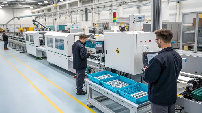
Quick answer: A production hot runner requires a documented sequence that proves every heater and thermocouple identity, brings the system to stable temperature without excessive residence, establishes balanced gates, protects against leakage and defines material-specific color-change and shutdown limits. Treat the controller recipe as one part of the validated system, not as proof that the manifold and gates are healthy.
Release Decision Matrix
| Validation stage | Required evidence | Release risk |
|---|---|---|
| Electrical identity | Zone map, resistance/continuity and thermocouple response | Cross-wired or uncontrolled heating |
| Thermal startup | Approved ramp/soak, actual response and material readiness | Cold restriction or excessive residence |
| Gate balance | Cavity fill/weight, gate appearance and process trace | Cavity variation or frozen/open gate |
| Change/shutdown | Purge endpoint, hold time, restart result and protected state | Contamination, degradation or leakage |
Approval Checklist
- Match mold, cable, controller and document zone identities.
- Complete authorized electrical checks before heat-up.
- Trend actual zone response through ramp and soak.
- Synchronize resin, barrel, mold and hot-runner readiness.
- Compare gate and cavity behavior using controlled samples.
- Define evidence-based color-change acceptance and segregation.
- Set safe leak, idle, shutdown and restart reactions.
- Revalidate affected zones after repair or component replacement.
Identify the Complete Hot-Runner Configuration
Record manifold, nozzle, tip and valve-gate configuration; controller and connector; heater and thermocouple zone map; resin and color; gate details; and approved machine interface. Match zone labels on the mold, cable, controller and documentation.
Retain supplier instructions for the installed system and approved replacement components. Similar heaters or tips are not interchangeable by appearance alone, and an undocumented repair can change heat delivery or flow geometry.
Verify Electrical and Thermal Response
Before heating, perform authorized continuity, resistance, insulation and thermocouple checks using safe procedures and equipment. Compare results with controlled references and investigate reversed, shared, open or unstable signals rather than bypassing alarms.
During heat-up, trend each actual zone against its target and time. Watch for zones that heat unusually fast, lag, overshoot or respond to the wrong control output. Confirm the mold is properly assembled, cooled and protected for the approved sequence.
Control Material Readiness and Residence
Prepare the exact resin according to supplier handling guidance and synchronize barrel, mold and hot-runner readiness. Define what happens during delays so material is not held at process temperature indefinitely while another system is unavailable.
Use a startup purge and first-shot segregation plan. Record interruption time, thermal state and restart disposition. Heat-sensitive, filled or color-critical materials may require different limits, so avoid one universal shutdown rule.
Prove Gate and Cavity Balance
Run controlled partial-fill and stabilized-cycle studies appropriate to the mold. Compare cavity progression, part mass, pressure response, gate vestige, stringing, drool and valve timing. Separate thermal balance from dimensional compensation.
Investigate a lagging gate through zone response, tip condition, material obstruction, valve motion and local mold temperature. Raising one setpoint until weights match can hide a restriction and increase degradation or leakage risk.
Validate Color and Material Changeover
Define the previous and next resin/color compatibility, required purge material, machine and hot-runner sequence, segregated shots and visual or measured acceptance. Count accepted endpoint evidence rather than relying only on a fixed number of purge shots.
Inspect dead spots, valve-gate behavior and cavity-specific streaking. Document waste, time and recurrence. If changeovers are frequent, their cost and risk belong in gating and production planning, not only in setup instructions.
Plan Leakage Response, Shutdown and Maintenance
Define pressure, temperature, alarm and observation signals that require a controlled stop. If leakage is suspected, isolate energy and follow trained procedures; do not continue cycling to clear material from an unknown leak path.
Specify approved idle, shutdown, cool-down and restart states by material and system. Keep critical spares, torque or assembly instructions, service history and repair evidence. Revalidate affected zones and gates after intervention before normal production release.
Illustrative Hot-Runner Zone Mapping Error
Illustrative engineering example—not a claimed CKMOLD customer result: After a cable repair, one controller zone appears stable but a neighboring nozzle overheats. A heat-response check shows that two labels were exchanged between the cable and documentation. The team corrects identity, inspects affected material paths and repeats startup and cavity-balance validation before releasing the mold.
Supporting Review Resources
Questions Before Approval
Can all hot-runner zones use one temperature?
Not automatically. Targets depend on resin, system design, gate behavior and verified thermal response; zone equality is not the same as physical balance.
How is a hot-runner gate imbalance diagnosed?
Compare fill and part evidence with zone response, tip condition, valve motion, local mold temperature and process traces before compensating setpoints.
When is a color change complete?
When the defined cavity-specific visual or measured acceptance is met under stable conditions, not merely after a predetermined purge count.
What should happen after a heater replacement?
Confirm correct component and assembly, repeat electrical identity and response checks, then verify affected gate and cavity behavior before release.
Apply the Hot Runner Startup and Color-Change Validation for Production Molds review to your released design. Share the function, exact resin, annual volume, CTQs, cosmetic limits and launch timing through the CKMOLD project form. If CAD is relevant, send it directly to jerry@ckmold.com; the form does not require an upload.