
Home / Engineering Support / Injection Mold Design for Stable Production
Injection mold design converts an approved plastic part and DFM basis into a tool architecture that can fill, cool, open, eject and be maintained on the intended molding machine. Every interface affects another: a gate choice changes flow and vestige; an action changes cooling, wear and service access.
CKMOLD develops the mold design with controlled approval gates before machining. The destination plant, component standards and document package receive added emphasis when the mold will be exported.
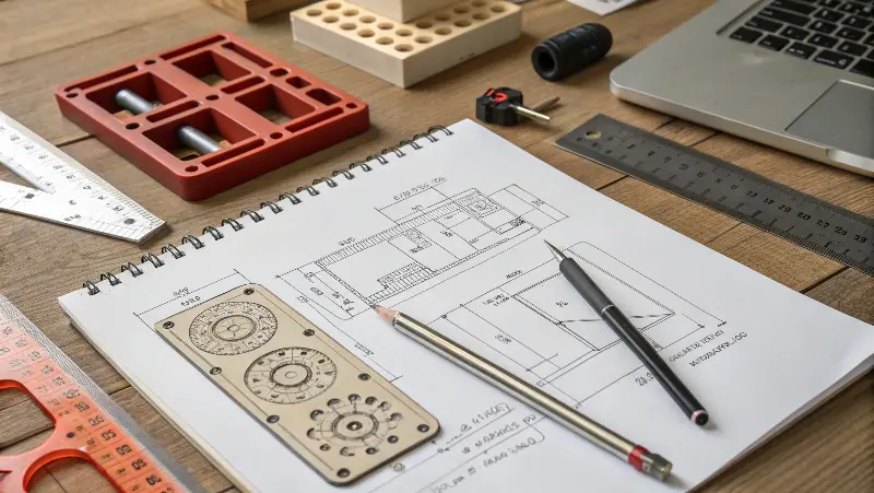
Approved part CAD, DFM and machine data
Mold architecture reviewed as connected subsystems
Customer approval before machining commitment
Revision identity maintained through changes
Reviewed by CKMOLD project engineering • Last updated August 2026
The design begins with approved geometry, resin, demand, appearance, critical dimensions, expected mold life and the production or export destination.
Core/cavity split, inserts, actions, wear surfaces, cooling circuits and ejection are organized so the tool can be built, fitted, serviced and corrected.
These are not isolated checklist items. Each decision is reviewed against filling, heat removal, motion, part release, service life and the press that will run the tool.
Place the split and shutoffs around geometry, appearance, sealing, machining access and flash risk.
Select gate type, position and runner layout around flow path, weld location, shear, vestige and de-gating.
Route circuits around heat load, steel thickness, inserts and actions while preserving drilling access and leak control.
Balance pins, sleeves, stripper systems or other release methods against draft, marks, deformation and safe part handling.
Resolve side actions, guidance, travel, locking, wear and timing for undercuts without sacrificing cooling or serviceability.
Where threaded geometry requires it, evaluate mechanism, drive, timing, thread release and press compatibility as a distinct scope.
Confirm brand/model, nozzle layout, gating, temperature control, electrical connections, spare parts and receiving-plant standards.
Match resin wear/corrosion, finish, mold life and maintenance strategy to traceable materials and agreed standards.
Check mold envelope, tie bars, locating ring, nozzle, clamp, ejector, daylight, water, electrical and handling interfaces.
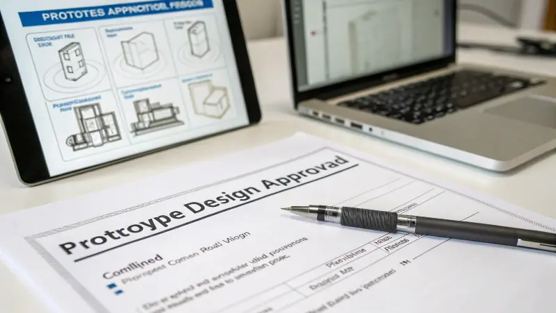
A mold-design release typically includes the agreed 3D assembly and the 2D information required for construction, interfaces, components and customer review. The exact file set depends on whether CKMOLD will retain the tool or hand it over as an export mold.
BOM references, purchased-component models, circuit identification and revision records reduce ambiguity during build and later maintenance. For export tooling, destination naming, standards and document formats should be decided before final approval—not reconstructed after the mold is complete.
Identify the approved part revision, resin, appearance zones, cavities, press and component standards.
Review parting, gate, runner, actions, ejection, cooling direction and the main mold envelope before detail work.
Resolve interfaces, circuits, component models, tolerances, steel, sensors/electrics and service access.
Record customer approval, released files and any remaining assumptions before steel cutting or irreversible work.
Side actions, hot runners, unscrewing or cavity multiplication can be justified by geometry, cosmetic requirements, output or downstream labor.
A part revision, different gate, insert strategy or lower cavity count can improve cooling access, reliability, mold cost or corrective flexibility.
Released steel, components, datum strategy and manufacturing drawings become the basis for machining, fitting and assembly.
The design determines the press match, trial setup, action checks, cavity identity and technical questions to answer at T0/T1.
Cooling, venting, ejection, wear and service access affect the process window, maintenance and repeatability long after first samples.
The part revision, resin, finish, critical requirements, expected quantities, cavity strategy, mold ownership and production destination should be defined. Open DFM items must either be resolved or explicitly accepted as risk.
Customer-specified component standards can be reviewed and incorporated when identified in the RFQ and approved component list. Availability, exact models and exceptions must be confirmed before design release.
The brand and model are not assumed from a generic page. Selection depends on resin, gate/nozzle layout, control system, destination support, customer standard, spare-parts preference and commercial scope.
The deliverable set is defined in the quotation. Export mold programs normally require a broader handover package than tools retained for CKMOLD production. File formats, BOM and revision status should be stated before purchase.
The change is treated as a controlled revision. CKMOLD evaluates affected steel, components, timing, cost and prior work, then obtains approval before changing the mold basis.
Send the part files, resin, quantities, finish, critical dimensions, target press information and required component standards. Include any existing DFM or moldflow report so the design basis is visible.
Use this short form for a general inquiry. For a quotation, complete the full RFQ and email any 3D/CAD files separately to jerry@ckmold.com.
Join our mailing list and receive a 10% discount on your next mold or CNC project.