
Home / Plastic Parts / Insert Molding and Overmolding Services
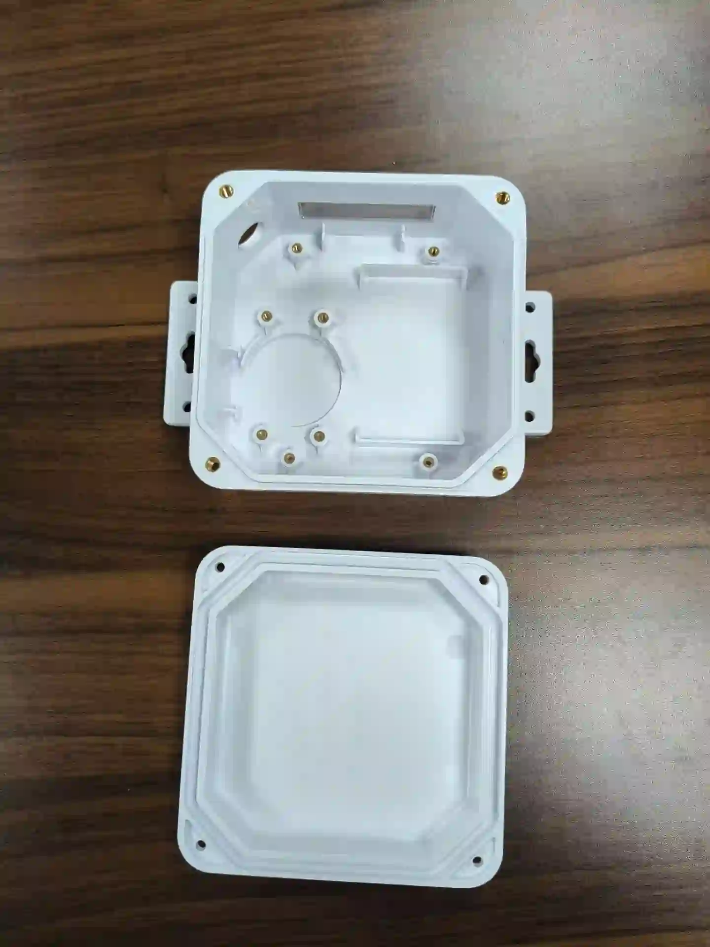
Insert molding places a separate component—often a metal nut, pin, terminal or bushing—into the mold before plastic forms around it. Overmolding adds a second material over a molded or supplied substrate to create grip, sealing, protection or an integrated interface.
CKMOLD evaluates positioning, retention, sealing, material compatibility, loading and verification for these processes. Two-shot molding is not presented as a standard in-house capability on this page because the required dedicated equipment has not been verified.
Nut, pin, bushing, terminal or customer component
TPE/TPU or compatible material over a substrate
Geometry and process resist movement during fill
Position, dimensions, bond and function checked by scope
Reviewed by CKMOLD project engineering • Last updated August 2026
A separate component is located in the cavity and encapsulated or captured by the injected plastic.
A second material is molded over a rigid or flexible substrate for grip, seal, impact, insulation or integrated handling.
Use pins, shoulders, nests, thread features or other deterministic datums so the insert is not located only by operator feel.
Review exposed area, flow direction, support and clamp so the insert does not tilt, float or shift under injection pressure.
Control shutoffs around metal to limit flash without damaging the insert, blocking threads or creating unsafe tool contact.
Define cleanliness, plating/coating, burr limits, incoming dimensions and the supplier responsibility for insert quality.
Manual loading can fit lower demand or complex handling; automation requires stable presentation, detection, cycle and business justification.
Use orientation features, sensors or checking methods where a missing, reversed or wrong insert presents meaningful risk.
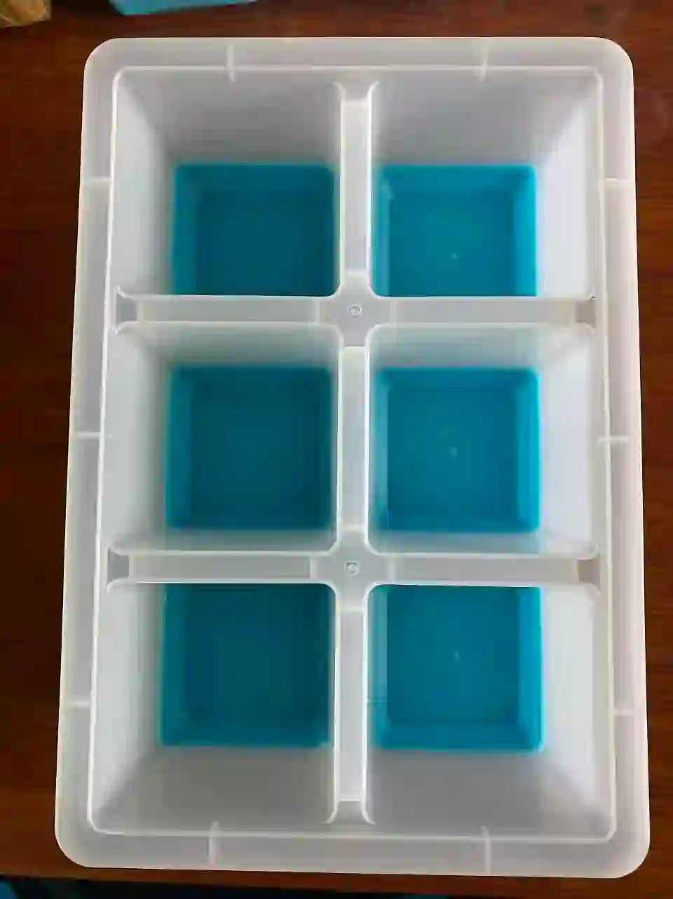
TPE or TPU grades differ in polarity, hardness, flow, temperature resistance and the substrates they are formulated to bond with. Supplier compatibility guidance and sample testing are more reliable than assuming that every soft material will chemically adhere to ABS, PC, PC+ABS, PA or another base.
When chemical bonding is uncertain or service conditions are demanding, mechanical locks—holes, grooves, wraparound edges or captured geometry—can make retention less dependent on surface chemistry. The design still needs venting, controlled overmold thickness, draft and shutoffs that prevent feather-edge flash.
Identify insert/substrate drawings, exact materials, supplier condition, orientation and protected surfaces.
Develop location, support, shutoff, encapsulation and mechanical lock around the intended molding direction.
Choose manual or automated presentation, mistake-proofing, detection and safe operator access by demand and risk.
Evaluate movement, flash, bond, voids, appearance, dimensions and the actual service test on labeled samples.
Approve insert source, material grades, loading/checking method, inspection and packaging that protects the interface.
Plastic housings and brackets that need reusable threads, load-spreading bushings or retained metal interfaces.
Connectors and electrical components where insert position, insulation, sealing and damage prevention are critical.
Handles, protective edges, gaskets and touch surfaces that use a compatible soft material over a rigid substrate.
Provide the plastic part and insert CAD/drawings, insert material and supplier condition, plastic grade, quantities, loading orientation, critical insert position, protected surfaces and any pull-out, torque, electrical or sealing requirement.
No. Bonding is grade-specific and affected by substrate chemistry, additives, moisture, contamination, molding temperature and geometry. Use resin-supplier compatibility information plus project-specific trials; add mechanical retention when needed.
This page does not claim two-shot molding as a standard verified capability. CKMOLD can review the part and discuss insert or sequential overmolding routes; any specialized two-shot equipment requirement must be confirmed separately before quotation.
Manual loading may be practical for lower volumes, large or variable inserts, or a process where automation cannot be justified. The quotation must include cycle, operator access, mistake-proofing and detection requirements.
The method depends on function. It may involve visual coverage, peel or pull testing, sealing, torque, assembly or a customer-defined functional test. The test geometry, sample conditioning and acceptance limit should be agreed before production.
Enter exact resin grades, quantities, bond or retention requirements, critical dimensions, finish, loading preference and the approval test in the RFQ form. Email the part and insert/substrate files separately to jerry@ckmold.com.
Use this short form for a general inquiry. For a quotation, complete the full RFQ and email any 3D/CAD files separately to jerry@ckmold.com.
Join our mailing list and receive a 10% discount on your next mold or CNC project.