
Home / Engineering Support / Plastic Part Design Support for Injection Molding
CKMOLD helps customers turn a mature concept, sample, 2D drawing or existing 3D model into plastic-part CAD that is ready for formal DFM and mold quotation. The service concentrates on molded geometry, part function and manufacturing preparation.
It is not a substitute for complete electronic, mechanical-system or industrial-design development. The customer remains responsible for product requirements, safety, regulatory strategy and system-level validation that sit outside the molded component.
STEP/STP, IGES, X_T, 2D drawing or sample
Molded-part geometry and manufacturability preparation
Controlled CAD revision and open-issue record
Not full electronics or industrial design
Reviewed by CKMOLD project engineering • Last updated August 2026
The work is organized around the maturity of the input. A physical sample requires different decisions from a released assembly model, so the first step is to define what may change and what must remain fixed.
Inventory the available sample, sketch, 2D drawing, CAD revision, interface dimensions and product requirements.
Build or revise the plastic part around nominal walls, transitions, ribs, bosses, snaps, openings and intended molding direction.
Check assembly stack-up, fastening, sealing, load paths, cosmetic zones and the features the customer treats as critical.
Decide whether a printed or machined prototype is needed for form and fit before the geometry is committed to tooling.
Release the agreed CAD revision and list any assumptions that must continue into DFM and mold design.

Uniform nominal walls, gradual transitions and supported features help manage sink, warp, filling and cooling. Draft is coordinated with texture and ejection direction. Ribs and bosses are sized and connected so they provide function without creating unnecessary mass behind a cosmetic surface.
Where assembly features drive the part, CKMOLD reviews the mating interface and tolerance direction before recommending a geometry change. A stronger rib or tighter dimension is not automatically better if it creates stress, visual read-through or an unrealistic molding window.
Develops or revises the product-side CAD so the molded component can meet function, assembly and appearance requirements.
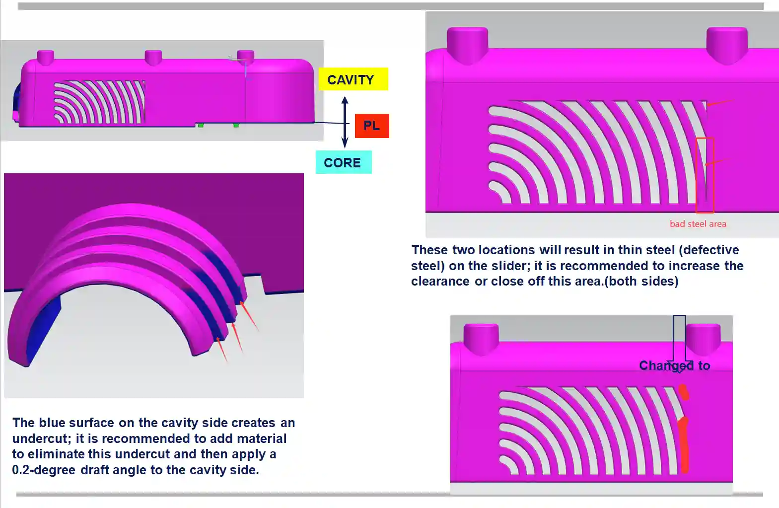
Tests the released or near-released geometry against manufacturability, defect risk and proposed molding strategy before tooling approval.
Creates the tool architecture that will form, cool, eject and maintain the approved part on the intended molding machine.
Identify datums, mating surfaces, sealing lands, latch points, fastener axes and visual surfaces so a change does not solve one problem by moving another.
Review insertion direction, access for screws or stakes, snap engagement, cable or insert clearance, and the tolerance path across mating parts.
Separate stiffness, impact, heat, chemical, UV, friction, transparency and appearance needs before a family or grade is selected.
Locate parting lines, gates, ejector marks, texture boundaries and weld-line risk away from controlled cosmetic zones where possible.
Record protected interfaces and customer-approved change limits. Reverse engineering from a sample should not silently alter fit or ownership assumptions.
Use 3D printing or CNC for form and fit; choose molded prototype tooling when production resin and injection behavior are the unknowns.
The working record should identify the input revision, questions, customer decisions and the released output. Depending on scope, the deliverable may include updated 3D CAD, selected 2D details, marked screenshots, a change log and a list of unresolved assumptions for DFM.
CKMOLD does not treat every sketch as authority to redesign the product. When a decision affects a protected assembly interface, appearance requirement or regulatory claim, the customer approves the change before the file becomes the mold basis.
Conceptual engineering visual used to explain molded-part preparation; not a customer drawing or measurement record.
Yes, when the customer has the right to reproduce the part and can define which dimensions, interfaces and performance characteristics must be preserved. Sample-based work still needs an agreed measurement basis and may not reveal internal material or tolerance intent.
No. CKMOLD’s scope is the plastic molded component and its preparation for tooling. Electronics, firmware, industrial styling, complete mechanism design, safety analysis and regulatory approval remain outside this service unless separately provided by the customer’s qualified team.
Part design develops the product geometry. DFM evaluates near-released geometry against molding, tooling and defect risks. Significant part changes identified during DFM return to a controlled design revision before mold design proceeds.
No. A prototype is useful only when it answers a material, fit, ergonomic or functional question that cannot be resolved confidently in CAD. Mature components with clear interfaces may proceed directly to DFM and tooling approval.
The customer approves product requirements and the CAD revision used as the mold basis. CKMOLD records manufacturability recommendations and should not release steel cutting on an unapproved geometry.
Complete the RFQ with the dimensions and surfaces that cannot move and explain whether you need CAD development, DFM or a mold quotation. Then email STEP/STP, IGES/IGS or X_T files, drawings, sample photos and assembly context separately to jerry@ckmold.com.
Use this short form for a general inquiry. For a quotation, complete the full RFQ and email any 3D/CAD files separately to jerry@ckmold.com.
Join our mailing list and receive a 10% discount on your next mold or CNC project.