
Home / Mold Tooling / Multi-Cavity Injection Molds for Scalable Part Production
A multi-cavity mold can reduce molding cost per part by producing several parts in each cycle, but only when demand, press capacity, runner strategy, cooling, part consistency and maintenance support the higher tooling investment. More cavities are not automatically more economical.
CKMOLD evaluates cavity count as a system. The design must fill and cool cavities consistently, identify each cavity for inspection, and remain serviceable when one insert or gate requires correction.
Cavity count starts with required output and batch pattern
Flow and cooling must be comparable by cavity
Cavities numbered for samples and inspection
Inserts and spares planned for service continuity
Reviewed by CKMOLD project engineering • Last updated August 2026
Use annual demand, batch size, available production time and delivery pattern—not a generic high-volume label.
Review part wall, material, cooling and handling before assuming cycles available per hour.
Confirm projected area, clamp, shot, plasticizing, mold envelope, tie bars and utilities for the proposed layout.
Compare tooling investment, runner waste, hot-runner cost, maintenance and unit-production effect.
Release the cavity strategy only when balance, inspection, spares and future demand assumptions are visible.
Can reduce purchased-system complexity and may suit some materials, quantities or simpler layouts, but runner weight, regrind policy, de-gating and balance affect economics.
Can reduce runner waste and improve direct gating options, but adds thermal, electrical, maintenance, supplier and spare-parts considerations.
Comparable flow path and pressure loss help cavities begin and complete filling together. Geometric balance is checked against part layout and gating.
Gate condition, venting, material behavior and part variation can disturb fill even when runner lengths look equal. Moldflow may be justified.
Circuit layout, steel mass, inserts, actions and local wall thickness affect cooling and shrinkage by cavity.
Part release and removal should not damage one cavity’s parts or force an inconsistent manual operation across the mold.
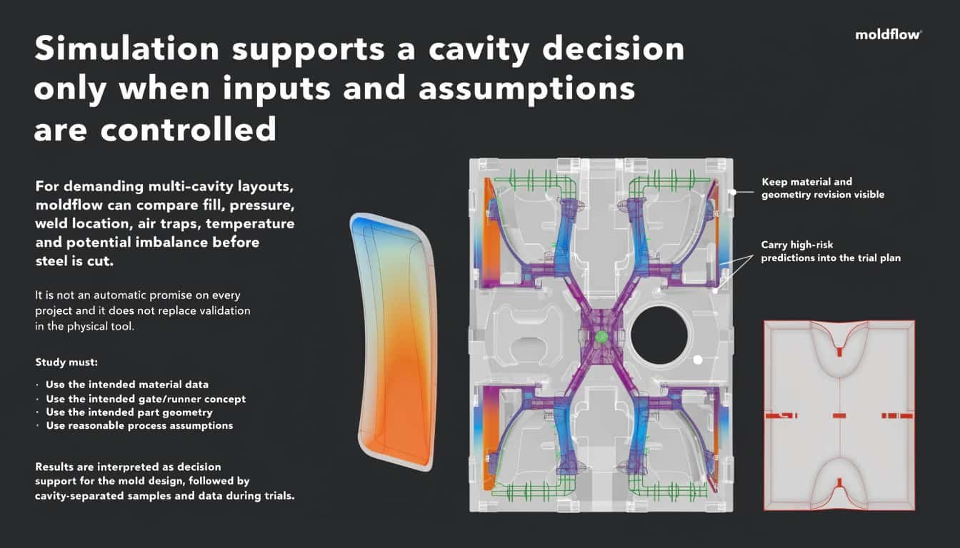
Conceptual flow-analysis illustration; actual moldflow is separately scoped and based on project-specific inputs.
For demanding multi-cavity layouts, moldflow can compare fill, pressure, weld location, air traps, temperature and potential imbalance before steel is cut. It is not an automatic promise on every project and it does not replace validation in the physical tool.
The study must use the intended material data, gate/runner concept, part geometry and reasonable process assumptions. Results are interpreted as decision support for the mold design, followed by cavity-separated samples and data during trials.
Forecast and order pattern support the output, and the buyer can use the capacity without creating excessive finished inventory.
Geometry, resin, finish and interfaces are mature enough that late changes will not multiply correction cost across many cavities.
The production location can service the tool, source components and manage cavity-specific repairs or spare inserts.
The answer depends on annual demand, batch schedule, cycle basis, part/runner weight, press capacity, tooling budget, maintenance and acceptable unit cost. CKMOLD evaluates alternatives rather than selecting cavities from quantity alone.
No. Hot runners can reduce runner waste and support certain gate layouts, but cost, maintenance, material sensitivity, thermal control and destination support matter. Cold runners may remain practical for some programs.
No. Gate condition, cavity temperature, venting, steel variation, resin behavior and ejection can create differences. Balance is confirmed through design analysis and cavity-separated trials.
Cavities are numbered where practical, and trial samples or production records can be separated by cavity. The inspection plan focuses on dimensions and appearance that are sensitive to cavity variation.
Often, replaceable cavity/core inserts and spare planning can localize work, but repairability depends on the original architecture and damage. The affected cavity must be revalidated after repair.
Send CAD, resin, part weight if known, initial and annual demand, required delivery pattern, target press, finish, critical dimensions and preferred runner standards.
Use this short form for a general inquiry. For a quotation, complete the full RFQ and email any 3D/CAD files separately to jerry@ckmold.com.
Join our mailing list and receive a 10% discount on your next mold or CNC project.