Struggling with complex mold designs? This can lead to costly errors and project delays. This guide will simplify the essentials for you.
Mastering plastic injection mold design and manufacturing involves understanding the core process, selecting suitable materials, applying Design for Manufacturability (DFM) principles, and optimizing mold elements like gating and cooling for efficient, high-quality production. This ensures your projects succeed.
Understanding these key areas is fundamental for anyone in this field, from product designers like Jacky to seasoned manufacturing professionals. I’ve spent years in this industry, starting on the factory floor and later building my own mold and CNC trading company. I’ve seen firsthand how a solid grasp of these principles can make or break a project. My goal with CKMOLD is to share this knowledge, helping you navigate the complexities and achieve success. So, let’s dive into what makes a great mold design.
Why is Deeply Understanding the Injection Molding Process So Fundamental?
Feeling lost in the basics of injection molding? This confusion often causes design flaws and production issues. Let’s clarify the core process right now.
A deep understanding of the injection molding process is absolutely vital. It involves melting plastic, injecting it under high pressure into a precisely machined mold, allowing it to cool and solidify, and then ejecting the finished part. This knowledge prevents costly design mistakes and production delays.
To truly design effectively for injection molding, you need to grasp how the machine and the process work together. Think of it like this: an architect needs to understand construction methods to design a building that can actually be built. It’s the same for us in mold design.
The Injection Molding Cycle Explained
The process is a cycle, and each step is critical:
- Clamping: The two halves of the mold are securely closed by the clamping unit. This needs to withstand the immense pressure of the injected molten plastic.
- Injection: Plastic pellets are fed into an injection barrel, melted by heat and friction from a rotating screw, and then forcefully injected into the mold cavity. The screw acts like a ram during this phase.
- Dwelling (or Packing): After the cavity is filled, more material is packed in under pressure. This compensates for material shrinkage as it cools.
- Cooling: The molten plastic cools and solidifies, taking the shape of the mold cavity. Cooling time is a significant part of the cycle time.
- Mold Opening: The clamping unit opens the mold halves.
- Ejection: The solidified part is pushed out of the mold by an ejection system, often using pins or plates.
I remember when I first started, seeing this cycle in action was eye-opening. The speed and precision were incredible, but I also saw how a small miscalculation in design could halt the entire line. Understanding this cycle helps you anticipate potential problems and design solutions into the mold itself. For example, knowing how cooling affects cycle time will make you pay more attention to designing efficient cooling channels.How Do You Select the Perfect Plastic Material for Your Molded Part?
Choosing the wrong plastic material for your part? This common mistake can ruin product performance and lead to failures. Discover how to select materials wisely.
Selecting the perfect plastic involves carefully considering its mechanical properties, thermal resistance, chemical compatibility, electrical characteristics, aesthetic requirements, and overall cost, all matched to the part’s end-use application. This ensures functionality and durability.

The range of available plastic resins is vast, and each has unique characteristics. It’s not just about how the part looks; it’s about how it performs in its intended environment. I’ve seen projects where a seemingly small oversight in material selection led to significant issues down the line, like parts warping under heat or cracking under stress. That’s why a systematic approach is key.
Key Material Properties to Consider
When I help clients, we usually break down the selection process by looking at these properties:
- Mechanical Properties: Think about strength (tensile, flexural, impact), hardness, and stiffness. Will the part be under load? Does it need to withstand impacts?
- Thermal Properties: Consider the operating temperature range. Will the part be exposed to extreme heat or cold? This affects material stability and expansion/contraction.
- Chemical Resistance: What chemicals, solvents, or oils will the part encounter? Some plastics degrade quickly when exposed to certain substances.
- Electrical Properties: Is the part an insulator or does it need conductive properties? This is crucial for electronic components.
- Optical Properties: Does the part need to be transparent, translucent, or opaque? Some plastics offer excellent clarity, like PC or PMMA.
- Cost and Processability: The material cost per part and how easily it can be molded are always important business considerations.
Common Thermoplastics and Their Applications
Here’s a quick look at some widely used materials: Material Common Uses Key Characteristics Polypropylene (PP) Packaging, containers, automotive parts, fibers Good chemical resistance, fatigue resistance, low cost Polyethylene (PE) Bottles, bags, toys, films Versatile, low cost, good toughness (varies by density) ABS Enclosures, LEGO bricks, automotive trim Good impact strength, toughness, surface finish Polycarbonate (PC) Eyewear lenses, medical devices, electronic housing High impact strength, transparency, heat resistance Nylon (PA) Gears, bearings, automotive components, fasteners Good strength, wear resistance, temperature stability I recall a project involving a casing for an outdoor sensor. The initial material choice didn’t account for prolonged UV exposure and temperature swings. The parts started cracking after just a few months in the field. We had to re-evaluate and switch to a UV-stabilized grade of ASA (Acrylonitrile Styrene Acrylate), which is similar to ABS but with much better weather resistance. This experience underscored the importance of thoroughly understanding the end-use environment.
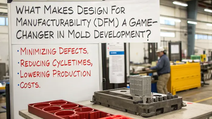
What Makes Design for Manufacturability (DFM) a Game-Changer in Mold Development?
Are your innovative part designs proving difficult or expensive to mold? This often inflates costs and extends timelines unnecessarily. DFM principles are your practical solution.
Design for Manufacturability (DFM) is a critical proactive approach. It involves designing parts to be as easy and economical to mold as possible, right from the start. This minimizes defects, reduces cycle times, and lowers overall production costs.

DFM isn’t just a buzzword; it’s a foundational philosophy in modern manufacturing. As a designer or engineer, incorporating DFM principles means you’re thinking about the manufacturing process while you’re still in the design phase. This collaboration between design and manufacturing perspectives is where the magic happens. I’ve seen too many brilliant designs fail or become excessively expensive because basic DFM rules were ignored.
Core DFM Principles for Injection Molding
When I review a design for moldability, these are some of the first things I look at:
- Uniform Wall Thickness: This is perhaps the most important rule. Consistent wall thickness helps prevent issues like sink marks, warping, and voids. Molten plastic flows more evenly and cools more uniformly. If varying thicknesses are unavoidable, the transition should be gradual.
- Draft Angles: These are slight tapers applied to the vertical walls of the part, in the direction of mold opening. Typically, 1 to 2 degrees is sufficient for most surfaces, but textured surfaces might need more. Draft angles allow the part to be easily ejected from the mold without drag marks or damage.
- Radii and Corners: Sharp internal corners are stress concentrators and can make mold filling difficult. Generous radii on both internal and external corners improve material flow, reduce stress, and increase the strength of the part. They also make the mold easier to machine and more durable.
- Ribs and Bosses: Ribs can be used to increase stiffness and strength without increasing overall wall thickness. Bosses are typically used for mounting or alignment. Both should follow DFM guidelines (e.g., rib thickness around 50-60% of the adjoining wall, height limits, draft angles).
- Undercuts: These are features that prevent the part from being directly ejected from the mold, like a side hole or a snap-fit latch. While sometimes necessary, they add complexity and cost to the mold, often requiring side-actions or lifters. DFM aims to minimize or cleverly design undercuts if they are unavoidable.
Implementing DFM isn’t about restricting creativity; it’s about channeling it in a way that’s practical for production. The benefits are significant: reduced tooling costs, faster production cycles, higher quality parts, and fewer headaches for everyone involved.How Can You Optimize Critical Mold Design Elements for Peak Production Efficiency?
Are your current molds leading to inefficient production cycles or inconsistent part quality? This often means slow output and higher per-part costs. Optimizing your mold design is the key to improvement.
Optimizing critical mold design elements like the gating system, cooling channels, and venting strategy is absolutely essential for achieving peak production efficiency. A well-designed mold minimizes cycle times, reduces part defects, and extends the operational life of the tool.

Once you have a part designed with DFM principles in mind, the next step is to design the mold itself. This is where a deep understanding of how plastic flows, cools, and ejects becomes paramount. I’ve worked on many molds over the years, and the difference between a merely functional mold and a highly optimized one is often found in the details of these critical elements. An optimized mold doesn’t just make parts; it makes them quickly, consistently, and cost-effectively.
Optimizing Gate Design and Location
The gate is the opening through which molten plastic enters the mold cavity. Its design and location are critical.
- Types of Gates: There are many types, including edge gates (simple, on the parting line), submarine (or tunnel) gates (de-gate automatically during ejection), hot runner gates (keep plastic molten right up to the cavity, reducing waste and cycle time but adding cost), and direct sprue gates (for single-cavity molds). The choice depends on the part material, geometry, cosmetic requirements, and production volume.
- Impact of Gate Location: The gate should be placed to ensure complete and balanced filling of the cavity. It should ideally be located in the thickest section of the part to allow for proper packing. Poor gate location can lead to weld lines, air traps, jetting, or warpage. It also affects the cosmetic appearance, as a gate mark will be visible.
Designing Effective Cooling Systems
Cooling typically accounts for the largest portion of the injection molding cycle time.
- Importance of Cooling: Efficient and uniform cooling is vital for minimizing cycle time and controlling part quality (e.g., preventing warpage and ensuring dimensional stability).
- Cooling Channel Design: Channels should be designed to provide even cooling across the part surface. They should be placed as close to the cavity surface as possible without compromising mold strength. The diameter and layout of the channels are important, and sometimes conformal cooling (channels that follow the contour of the part) is used for complex geometries.
The Role of Venting
As molten plastic fills the cavity, the air and any gases generated from the plastic must escape.
- Why Venting is Needed: Inadequate venting can lead to trapped air, resulting in incomplete filling (short shots), burn marks (from compressed, superheated air), or poor surface finish.
- Common Venting Strategies: Vents are typically small channels machined into the parting line of the mold. They must be deep enough to let air escape but shallow enough to prevent plastic from flowing out. Ejector pins and other mold components can also be designed to aid venting.
Thinking through these elements – gating, cooling, and venting – as an integrated system is key. Each affects the others, and together they determine the efficiency and quality of the molding process. I remember a case where we were struggling with long cycle times. By re-evaluating and optimizing the cooling channel layout, we managed to shave off several seconds per part, which, over a long production run, translated into significant savings.Conclusion
Mastering mold design and manufacturing is a journey. It combines understanding processes, materials, DFM, and optimization for truly efficient and high-quality results every time.
