Do you want to prevent costly rework and injection molding production downtime? These issues are typically the result of unexpected problems like warpage or air traps that are devouring your bottom line. Proper mold flow analysis offers a solid solution to forecast and prevent these problems before they occur.
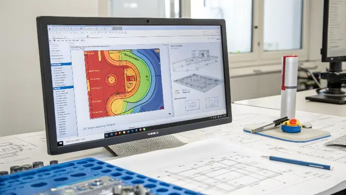
Mold flow simulation is an extremely valuable injection molding simulation technique. It predicts how molten plastic will flow inside the mold cavity. This "virtual preview" enables you to visualize potential flaws like warpage, air traps, or weld lines. By optimizing the process and design parameters in the early stages, you can save huge sums of money, prevent wasted time, and prevent expensive manufacturing headaches. It is also utilized to find the optimal gate size, runner size, and gate location.

While comprehending the potential of mold flow analysis is one thing, putting it into practice is quite another. And what tools can help you achieve the best resuLet’s take a closer look at these elements to see how you can actually become an expert in this technique for the best injection molding. We’ll dive into the specifics, making sure you get all the details.
How Do You Actually Perform Mold Flow Analysis?
Not sure where to begin with mold flow analysis for your injection molding designs? Blindly plunging in without a process can yield incorrect results and be a waste of time, failing to correct what you are attempting to correct. Following a step-by-step process for mold flow analysis enables you to receive the right information and make the right decisions.
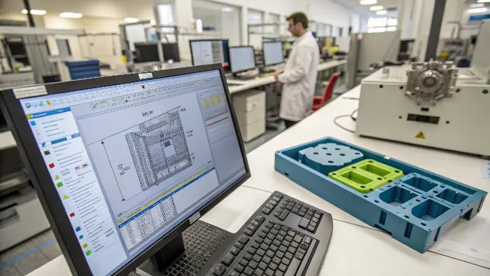
Mold flow analysis has several steps. First, you create your 3D model of your mold and part. Then you enter material properties, processing conditions (pressure and temperature), and gate locations. Then the software simulates the filling, packing, and cooling stages. Finally, you analyze the results to make decisions on potential problems and optimize the design for better manufacturability and quality part.

To really get a grip on mold flow analysis, let’s break down the process. It’s more than just clicking a button; it’s about careful preparation and interpretation. I remember when I first started in the mold industry, I thought the software would magically do all the work. But I quickly learned that the quality of the input dictates the quality of the output. If you feed it garbage, you’ll get garbage results.
Key Stages in Mold Flow Analysis:
-
Geometry Preparation:
- You start with a clean 3D CAD model of your plastic part. It’s really important to simplify complex features that don’t significantly impact flow but can slow down the simulation. Think about features that are very small compared to the overall part.
- Then, you’ll model the feed system: this includes the sprue, runners, and gates. Sometimes, for a more complete picture, the cooling channels are also modeled. This gives a more comprehensive analysis, especially for predicting cycle times and warpage.
-
Meshing:
- The software then takes your 3D model and converts it into a mesh, which is like a net of small elements. The finer the mesh (meaning more, smaller elements), the more accurate the results tend to be. However, a finer mesh also means the simulation will take longer to run. I’ve found that finding a good balance here is key, especially when deadlines are tight.
-
Material Selection & Process Parameters:
- You need to select the exact plastic material you plan to use. Most software has a large database, or you can input the specific properties of your material if it’s not listed.
- Then, you define the injection molding process parameters. These include things like melt temperature, mold temperature, injection pressure, packing pressure, and cooling time. These settings are absolutely critical for an accurate simulation.
-
Analysis & Interpretation:
- Once everything is set up, the software simulates the filling, packing, cooling, and sometimes warpage stages.
- After the simulation runs, you’ll look at various results. These can include fill time, pressure distribution, temperature distribution, locations of weld lines, potential air traps, shear rates, and predicted warpage. Interpreting these results correctly helps you pinpoint design flaws or suboptimal processing conditions. For example, identifying a potential air trap early on saved one of my clients a lot of trouble and money on a complex housing.
This systematic approach ensures you get valuable insights to optimize your mold design and process well before any steel is cut.
What is the Best Mold Flow Analysis Software to Use?
Overwhelmed by the variety of mold flow analysis software options available? Choosing the wrong software can mean investing in a tool that’s too complex for your needs, too simple to give you useful insights, or doesn’t fit well with your existing design workflow. Understanding the leading software options and their strengths helps you select the best fit for your design challenges.
Autodesk mold flow is the most popular software for simulating plastic injection molding process. Autodesk offers two prominent versions of the product, which are Mold Flow Adviser and Mold Flow Insight. Autodesk Mold Flow Adviser comes in Premium and Ultimate editions, and Mold Flow Insight comes in Standard and Premium editions. The software has unique features, but they all support importing CAD files containing geometric information
There are several excellent mold flow analysis packages with each having its own strengths. Some of the most widely used are Autodesk Moldflow, Moldex3D, and SOLIDWORKS Plastics. The "best" package is something that depends on your specific requirements, cost, complexity of the parts, and integration with your existing CAD tools. Reading user feedback and trial version testing can assist in making your decision. For instance, I’ve found Moldflow to be very detailed for detailed analyses.
There are other mold flow analysis software categories out there, as well. SolidWorks Plastics, Moldex3D and CoreTech Moldex3D, Sigmasoft, and Simcon simFLOW are some options. Creo mold flow analysis and ANSYS mold flow software are other options. This article is not recommending software or providing guidelines for its application. Rather, it illustrates how a quality mold flow analysis can improve injection molded parts.

Choosing the right software is a big decision, and it’s one that can significantly impact your design efficiency. When I was setting up my trading company, I spent a lot of time researching this because I knew it would be crucial for helping my clients optimize their parts and molds. There isn’t a single "best" software for everyone, as it really depends on what you’re trying to achieve and your specific circumstances.
Alternatively, you can skip the investment in mold flow analysis software entirely by asking CKMold to conduct a low-cost mold flow analysis through the quoting process. Start by uploading your design today.
Comparing Popular Mold Flow Software:
| Feature | Autodesk Moldflow | Moldex3D | SOLIDWORKS Plastics |
|---|---|---|---|
| Complexity | High (Offers many advanced features) | High (Very comprehensive simulation) | Medium (Well integrated with SOLIDWORKS) |
| Accuracy | Very High | Very High | Good for many common applications |
| Ease of Use | Steeper learning curve | Moderate learning curve | Easier for existing SOLIDWORKS users |
| Integration | Good with various CAD systems | Good with various CAD systems | Excellent with SOLIDWORKS |
| Typical User | Dedicated analysts, complex parts | Analysts, R&D, complex simulations | Designers, engineers needing quick checks |
| Key Strength | Industry standard, depth of analysis | Advanced meshing, detailed simulation | Ease of use for designers, fast setup |
For instance, if you’re a product designer like Jacky, with most of your time spent in the SOLIDWORKS environment, SOLIDWORKS Plastics might be a good starting point. Comparative ease of use and integration make it simple for everyday analysis without a steep learning curve. However, for really complex parts or if you want the most powerful simulation for high-risk applications, Autodesk Moldflow or Moldex3D is what experts suggest. Personally, I’ve utilized an enormous amount of Moldflow over the years and appreciate its ability to handle really challenging designs and gain in-depth insights. Consider your team’s current expertise, the type of problems you normally face (e.g., warpage, cooling efficiency), and, of course, cost. Most vendors offer trial versions, and I highly recommend you try them before purchasing. This will allow you to see what works best with your workflow.
What is the Significance of Flow Rate in Injection Molding?
Do you find that inconsistent flow rates are leading to defects in your molded parts? Incorrect flow rates can cause a host of issues like short shots where the mold doesn’t fill completely, flash where excess material seeps out, or uneven filling, all of which compromise part quality and increase scrap rates. Understanding and controlling the flow rate is essential for achieving consistent, high-quality injection molded components.
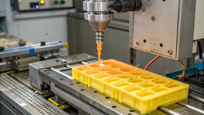
The flow rate in injection molding refers to the volume of molten plastic injected into the mold per unit of time. It’s a critical process parameter directly influencing filling patterns, pressure requirements, and potential defects. An optimal flow rate ensures the cavity fills completely and uniformly without degrading the material or causing excessive stress. It’s determined by factors like part geometry, material viscosity, and machine settings.

The flow rate isn’t just a number you set on the machine; it’s a dynamic factor that fundamentally dictates how your part forms inside the mold. I’ve seen projects where a slight miscalculation or a poorly chosen flow rate led to significant problems down the line, resulting in costly tool modifications or high reject rates. It’s all about how quickly or slowly the plastic fills the mold cavity.
Understanding Flow Rate Dynamics:
- Definition: Simply put, it’s how much plastic (usually measured by volume or weight) flows into the mold cavity over a certain period. Common units are cubic centimeters per second (cm³/s) or grams per second (g/s).
- Importance:
- Filling Pattern: A correct flow rate is crucial for ensuring the mold fills evenly and completely. If the flow rate is too slow, the plastic might cool and solidify prematurely, leading to short shots or visible flow marks. If it’s too fast, you risk issues like jetting (where the plastic shoots across the cavity instead of filling smoothly), material degradation due to high shear heat, or trapping air.
- Pressure: Injection pressure is proportional to the flow rate required to fill the part. In most cases, higher flow rates require higher injection pressures
- Cycle Time:Even though a higher flow rate will reduce the injection time part of the overall cycle, it is not always better if it generates defects. The goal is the most efficient cycle time that produces good parts
- Material Properties: Different plastics have different optimal flow rates due to their viscosity characteristics. What will be suitable for low-viscosity nylon will not be suitable for high-viscosity polycarbonate.
Factors Influencing Optimal Flow Rate:
| Factor | Impact on Flow Rate Choice |
|---|---|
| Part Wall Thickness | Thinner sections generally require a faster flow rate to ensure they fill before the plastic freezes off. |
| Gate Size & Type | Smaller gates restrict flow and may necessitate higher pressure or a slower, more controlled fill. The type of gate also matters. |
| Material Viscosity | Higher viscosity materials flow more slowly and may require adjustments to pressure and speed. |
| Melt Temperature | Higher melt temperatures reduce viscosity, allowing for easier flow. |
| Mold Temperature | Higher mold temperatures can allow for slower, more controlled flow as the plastic stays molten longer. |
| Machine Capability | The injection molding machine’s injection unit has limits on screw speed, injection speed, and available pressure. |
Mold flow simulation is worth its weight in gold in this scenario because it lets you visualize the flow front progression and the ideal injection speed profile. You can simulate different injection rates to see the impact on filling, pressure, shear rates, and potential defects without ever needing to cut steel to the mold. Having this predictive capability is a real game-changer for maximizing the process and removing guesswork.
The Relationship of Mold Flow Analysis to DFM
DFM (Design for Manufacture) is a design-for-manufacturing concept that demands cost and manufacturability at the product design level. DFM spans the entire product development process from conceptual design to detailed design, process planning, and production manufacturing phases.
In the production of plastic items (e.g., automotive, aerospace, medical, equipment, consumer, electronics, personal care, and most others), DFM during mold design is also crucial. Through DFM, product designs may be examined and improved for simpler manufacturing by designers. This includes manufacturability analysis, determination of the optimum manufacturing process, and design optimization of the product to reduce cost and manufacturing complexity.
In brief, mold flow analysis and DFM are both critical tools in mold design and mold manufacturing in the production of the automotive industry. They are complementary and can efficiently improve the quality and production efficiency of the mold and reduce the cost of production.
How Can You Improve or Eliminate Flow Marks in Injection Molding?
Are unsightly flow marks destroying the look and possibly the quality of your injection molded parts? Flow marks are surface imperfections that can cause part rejection, customer dissatisfaction, and added production costs, which no one would want. With your awareness of the most common causes of flow marks, you can take some measures to enhance or eliminate them effectively.
Flow marks are surface imperfections in the form of wavy lines, dull spots, or streaks on a shaped part, typically indicating the direction of plastic flow. They are typically produced by variation in cooling rate as the plastic is flowing across the mold surface, low injection rate, low melt or mold temperature, or inadequate gate location and design. Minimizing flow marks is a question of maximizing the parameters of uniform material flow and temperature distribution in the mold cavity. Mold flow analysis can pinpoint the causes.

Flow marks can be a real headache, especially for parts where aesthetics are important, like consumer electronics housings or automotive interiors. I remember a client who was struggling with this on a beautifully designed casing for a new gadget. The parts were functionally fine, but the visible flow marks made them look cheap and poorly manufactured. We used mold flow analysis to get to the bottom of it and find a solution.
Common Causes and Solutions for Flow Marks:
| Cause | Solution | How Mold Flow Analysis Helps |
|---|---|---|
| Low Melt Temperature | Increase melt temperature gradually, staying within the material manufacturer’s recommended range. | Simulates temperature distribution of the melt, showing if it cools too quickly as it flows. |
| Low Mold Temperature | Increase mold surface temperature. This allows the plastic to flow more easily across the mold surface before solidifying. | Analyzes mold surface temperature and its effect on the advancing flow front and cooling rate. |
| Slow Injection Speed | Increase injection speed. This helps the melt front advance more smoothly and uniformly, reducing differential cooling. | Visualizes the fill pattern at different speeds, identifying areas of hesitation or uneven flow that can cause marks. |
| Inadequate Gate Size/Location | Enlarge gate(s) or relocate them to promote smoother, less restricted flow and a more uniform filling pattern. Consider multiple gates for larger parts. | Helps optimize gate design and location for balanced filling, reduced shear heating at the gate, and uniform flow. |
| Non-Uniform Wall Thickness | Design parts with more uniform wall thickness where possible. Abrupt changes in thickness can cause variations in flow speed and cooling. | Highlights areas of varying thickness and their impact on flow velocity and cooling, which can lead to flow marks. |
| Material Issues (e.g., moisture) | Ensure proper material drying according to supplier specifications and good handling practices. Some materials are more prone to flow marks. | While not directly simulating moisture, analysis assumes ideal material properties; deviations in reality point to material issues. |
In that client’s case with the gadget casing, the mold flow analysis showed that a combination of a slightly low melt temperature and a gate that was a bit too small for the required flow path length was causing the issue. The plastic was cooling too much before it could properly replicate the mold surface. By suggesting an increase in melt temperature and a minor modification to enlarge the gate, we were able to significantly reduce the flow marks, much to the client’s relief. It’s often a combination of factors, and mold flow analysis is excellent at showing how these factors interact. It allows you to test potential solutions virtually before making costly physical changes to the mold or tying up a machine for trials.
Conclusion
Effective mold flow analysis is a valuable predictive tool in the injection molding world. It assists us in optimizing part and mold designs, predicting potential manufacturing defects such as flow marks or warpage, and optimizing processing conditions long before production occupies the mold. This ultimately saves precious time, material, and tooling expenses, and results in better quality injection molded parts, making it a necessary technique for contemporary manufacturing success.
