
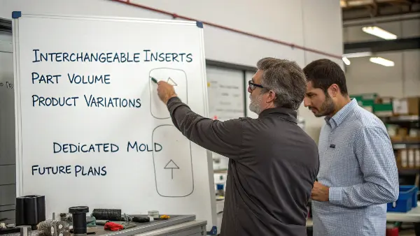
Managing multiple product variations with unique molds is costly and time-consuming. Each new version often means a new mold, leading to huge expenses and long downtimes between production runs. Interchangeable inserts offer a smarter way, letting you adapt one mold base for various parts. This approach saves significant time and money.
Interchangeable core and cavity inserts allow a mold to carry replaceable geometry instead of making every product change a modification to the main mold block. Used correctly, inserts can support product variants, protect high-wear regions, speed up repairs and simplify future corrections. They also introduce alignment, sealing, cooling and spare-part decisions that must be engineered from the start.
Related CKMOLD resources: mold design services, mold repair or modification, multi-cavity molds.
To use interchangeable inserts effectively, you must design a common mold base that securely houses swappable core and cavity components. This strategy allows you to produce different product variations, families of parts, or handle high-wear areas by simply replacing the inserts instead of the entire mold. Key design considerations include precise alignment features, robust locking mechanisms, and standardized connections for cooling and ejection systems. This approach significantly boosts flexibility, reduces tooling costs, and simplifies maintenance.
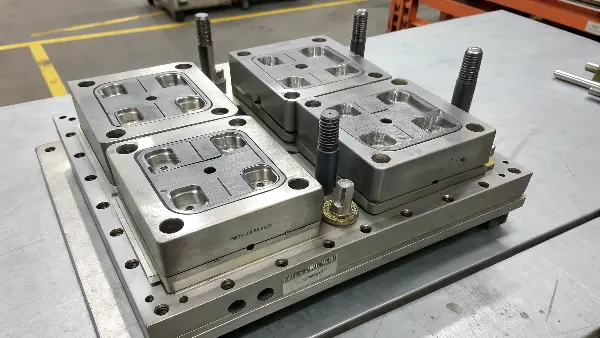
This all sounds great in theory, but putting it into practice requires careful attention to detail. You can’t just drop any insert into a mold base and expect it to work. There are specific design principles you need to follow to make sure everything fits reliably, runs efficiently, and lasts a long time.
How do you design inserts for suitable alignment and secure locking?
Your interchangeable inserts don’t align reliably, causing flash or part defects. This misalignment can damage the mold, create scrap parts, and halt production completely. This really defeats the purpose of having a flexible design in the first place. The solution is to implement robust locating and locking features that support precise and repeatable positioning every time you swap inserts.
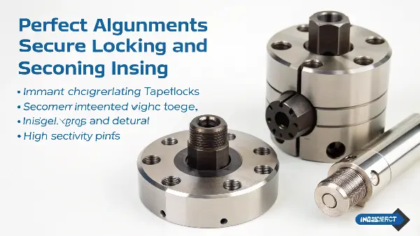
For suitable alignment, use a combination of primary and secondary locating features. Tapered interlocks or precision dowel pins serve as excellent primary locators for initial positioning. For final, high-precision alignment, use tight-tolerance locating rings or parting line locks. To secure the inserts, use strategically placed bolts that pull the insert firmly against its seating face. This ensures the insert doesn’t shift under injection pressure, guaranteeing part quality and mold safety.
Mastering Precision Alignment
Alignment is all about getting the insert in the exact right spot, every single time. We usually think about this in two stages: primary and secondary alignment. Primary alignment gets the insert roughly in place, making it easy for the operator to install. Secondary alignment provides the final, hair-splitting precision needed for a suitable seal.
For primary locating, I often use sturdy dowel pins or a tapered boss on the back of the insert. This guides the insert into its pocket smoothly. For the critical secondary alignment, we need something more robust. Tapered interlocks on the sides of the inserts are my go-to. As the mold closes, the tapers engage and force the inserts into their final, precise position.
Here’s a quick comparison of common methods:
| Alignment Method | Precision | Cost | Best Use Case |
|---|---|---|---|
| Dowel Pins | Good | Low | Primary alignment, smaller inserts |
| Tapered Interlocks | Excellent | Moderate | High-precision parting line seal, all sizes |
| V-Grooves | Very Good | Moderate | Aligning round inserts or specific features |
| Locating Ring | Excellent | High | Large inserts requiring central alignment |
Ensuring Robust Locking
Once the insert is reliably aligned, you have to lock it down so it doesn’t move an inch under the immense pressure of plastic injection. This is where your locking strategy comes in. It’s not just about using a few bolts; it’s about applying clamping force in the right places.
How can you standardize cooling and ejection systems for interchangeable inserts?
You’ve designed interchangeable inserts, but connecting cooling lines and setting up the ejection for each one is a nightmare. This hassle of custom connections for every insert leads to long changeover times, potential water leaks, and frequent setup errors. The whole system becomes inefficient. The solution is simple in concept but requires smart design: standardize your cooling and ejection interfaces within the mold base for quick and error-free changeovers.
To standardize cooling, use manifold plates with O-ring sealed ports that automatically connect to the inserts once they are installed. For ejection, design a universal ejector plate system in the mold base. This plate activates ejector pins that pass through the base and push on a standardized “actuator plate” or directly on the back of the insert’s own universal ejector pins. This approach eliminates manual hookups, dramatically speeding up mold changes.
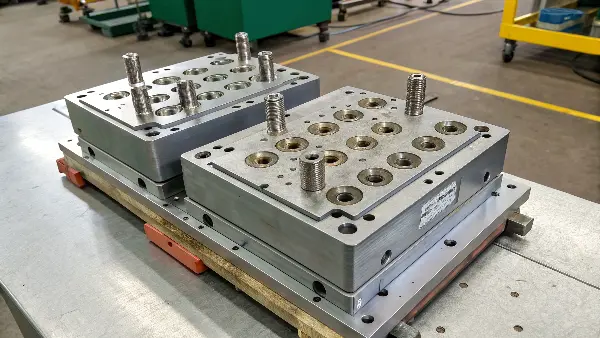
Thinking about these support systems from the beginning is what separates a good design from a great one. If an operator has to spend an hour hooking up tiny hoses every time they change an insert, you’ve lost most of the time savings you were hoping for. My goal is generally to make the changeover a “plug-and-play” process.
Designing a Universal Cooling Manifold
The secret to fast cooling hookups is to build the connections right into the mold. Instead of having hoses that connect directly to the insert, we create a master cooling manifold plate that sits behind it. This plate has a set of standardized water ports. The back of each interchangeable insert is then designed with a matching pattern of ports. When the insert is bolted in, high-temperature O-rings seal the connection between the insert and the manifold plate. Water flows from the main lines, through the manifold plate, into the insert, and back out again, all without a single external hose to connect.
This might sound complex, but the time savings are enormous. The key is careful design to ensure the O-rings are properly seated and that the ports are large enough to provide adequate flow for cooling.
| Factor | Standardized Cooling (Manifold) | Non-Standardized (Manual Hoses) |
|---|---|---|
| Changeover Time | < 5 minutes | 30-60 minutes |
| Leak Risk | Very Low (if well-maintained) | High (connection errors) |
| Setup Error | Almost Impossible | Common (wrong hose to wrong port) |
| Initial Cost | Higher | Lower |
Creating a Common Ejection System
Similar to cooling, we want to avoid reconfiguring the ejection system with every insert change. The best way to do this is with a generalized ejection setup in the main mold base. You design a master ejector plate that moves a standard pattern of ejector pins. These “master” pins don’t touch the plastic part directly. Instead, they pass through the mold base and push on an intermediate plate or a common ejector retainer plate that is part of the interchangeable insert itself.
When should you use interchangeable inserts over a dedicated mold?
You’re standing at a crossroads, unsure if the upfront investment in a complex interchangeable system is worth it. Making the wrong choice could mean spending too much on a mold you don’t need, or missing out on massive long-term savings and flexibility. The decision isn’t just about engineering; it’s about business strategy. It comes down to a clear-headed analysis of your part volume, product variations, and future plans.
Opt for interchangeable inserts when you have a family of parts with similar overall dimensions but different features, or when a product has multiple versions. It’s also ideal for prototyping multiple designs quickly. A dedicated mold is better for a single, very high-volume part with a long, stable production run where changeovers are rare. The higher initial cost of an insert system is justified by lower long-term tooling costs and faster changeovers.
This is a question I get asked all the time. There’s no single right answer for every project. But by looking at a few key factors, you can make a very informed decision. It’s about weighing the higher initial investment against the long-term operational savings.
The Economic Calculation
At its core, this is a break-even analysis. A high-quality interchangeable mold base is expensive. But each additional part variation only requires a relatively cheap set of inserts. A dedicated mold is cheaper initially, but you have to buy a whole new mold for every single variation.
Let’s imagine you have a family of five parts. A dedicated mold might cost $30,000 each, for a total of $150,000. An interchangeable system might have a base that costs $70,000, with each insert set costing $10,000. Your total tooling cost would be $70,000 + (5 x $10,000) = $120,000. In this case, you’ve already saved $30,000. The savings get even bigger as you add more variations. You also have to factor in the cost of machine downtime during changeovers. A faster changeover means more production time and more profit.
| Criteria | Interchangeable Insert Mold | Dedicated Molds |
|---|---|---|
| Initial Investment | High (for the base) | Low (per mold), but High (in total) |
| Cost per Variation | Low (cost of inserts only) | High (cost of a full mold) |
| Changeover Time | Fast (minutes) | Slow (hours) |
| Storage Space | Low (one base, small inserts) | High (multiple large molds) |
| Best for… | Part families, prototypes, frequent changes | Single high-volume, long-lifespan parts |
Strategic Application Scenarios
Beyond the raw numbers, there are several situations where interchangeable inserts are the clear strategic winner.
Family Molds: This is the classic use case. Think of a remote control shell. You might have one version with three buttons and another with five, but the overall size and shape are the same. You use one mold base and simply swap the cavity inserts that form the button details.
Prototyping: If you are developing a new product, you might want to test three different grip textures or logo placements. Instead of building three expensive prototype molds, you can build one base and three cheap sets of inserts. This lets you iterate and test designs much faster and more cheaply.
Use Inserts Where Change or Wear Is Real
Good candidates include product-identifying geometry, high-wear gates or shutoffs, interchangeable variants, textured surfaces and areas likely to need correction. An insert added only to make the CAD look modular may increase cost and create another interface without a useful maintenance benefit.
Design Alignment and Shutoff Like a Precision Joint
Locating features, taper, keys, bolts, support and preload determine whether the insert returns to the same position. Parting-line contact and shutoff geometry must resist flash under cavity pressure. The insert should be supported against movement, not held only by a fastener.
Plan Cooling and Thermal Continuity
A replaceable insert can interrupt cooling or create a hot spot. Independent channels, thermal contact, copper-alloy solutions or controlled interface design may be needed. Cooling connections and sealing must allow removal without damaging the mold or contaminating the circuit.
Build a Spare and Revision Strategy
Each insert should have an identification mark, drawing revision, steel and heat-treatment record, inspection data and storage location. Spare inserts are valuable only when they are interchangeable in practice; dimensions, surface, hardness and fit must be verified before release.
Measure the Lifecycle Value
Compare the insert architecture with a conventional block by product variants, expected wear, repair time, downtime, spare cost, correction probability and future volume. The best case is a tool that can change or recover quickly without sacrificing part repeatability.
Interchangeable Core and Cavity Inserts: Buyer Review Checklist
- Use interchangeable inserts for real variants, wear, texture or correction risk—not as decoration.
- Design location, support, preload and shutoff contact to prevent movement and flash.
- Preserve thermal performance with independent cooling or suitable interface design.
- Document insert ID, revision, steel, heat treatment, inspection and spare storage.
- Compare downtime, repair speed, spare cost and repeatability over the mold lifecycle.
FAQ
Do interchangeable inserts generally reduce mold cost?
Not necessarily. They can reduce future correction or variant cost, but the initial structure, fitting, cooling and inspection add complexity.
Where are inserts most useful?
They are useful for product variants, high-wear areas, textures, gates, correction-prone features and parts that need quick maintenance recovery.
Conclusion
Interchangeable core and cavity inserts are a powerful tool for modern manufacturing. They offer incredible flexibility, reduce long-term tooling costs, and simplify maintenance. Success depends on smart design, especially for alignment, locking, cooling, and ejection systems. Understanding when to use this strategy versus a dedicated mold is a key decision. When applied correctly, this technique can give you a major competitive advantage, and I hope these insights help you master it.