Have you ever invested a lot of time and money in a new mold, only to experience warpage or sink marks on the initial trial run? Such issues lead to costly rework and infuriating delays, sending your whole production schedule into a tailspin. Would it not be wonderful if you could anticipate such issues and correct them before a single piece of steel is ever cut? That is where mold flow analysis is your best friend.
Mold flow analysis is a high-tech simulation technology applied in injection molding. It simulates how molten plastic flows and fills a mold cavity when molding. The analysis enables the designer and the engineer to detect potential manufacturing defects, including warpage, sink marks, and air traps, at an early stage of design. Design optimization prior to the construction of the mold enables you to save a significant amount of time, lower costs, and produce higher-quality end parts. It is a crucial step for successful production.
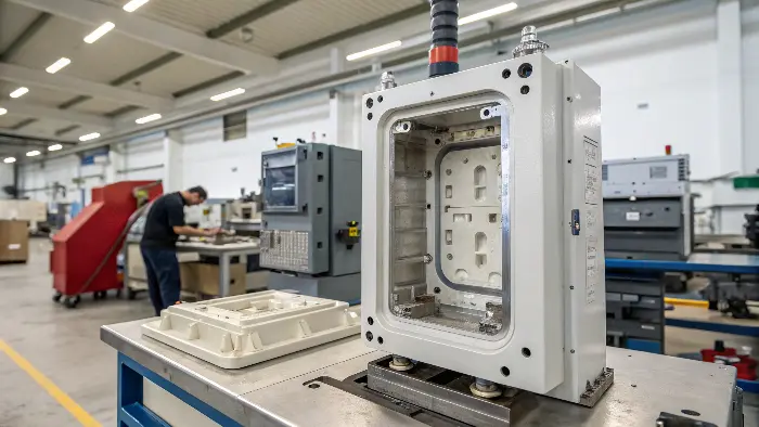
This simulation sounds powerful, and it is. However, in order to understand its worth, we must deconstruct it. Knowing what it is, why it is so important, and what it looks at will demonstrate how it can make your projects a guessing game to an exact science. Now let us get down to the details and find out how you can make this tool work in your favor and really master your molding projects.
What Exactly Is Mold Flow Analysis?
You’ve heard the term "mold flow analysis" bandied about during design reviews without actually having any clue what it is. Not being able to figure out what the process is has you stuck in the dark and unable to actually participate in design reviews. This can have you inadvertently letting costly mistakes slip through the cracks. Let’s cut to the chase. Mold flow analysis is simply a computer simulation of your molding process, enabling you to glimpse the future of your part.
Mold flow analysis, or MFA for short, is a computer-aided engineering (CAE) simulation. It uses specialized software to create a virtual replica of your part and mold. The software simulates the entire injection molding process: filling, packing, and cooling. It shows how the plastic material flows around in the mold, predicting its flow patterns, pressure, and temperature distribution. This test run simulation finds potential trouble before you spend money on expensive tooling, and thus it is an essential part of product development today.
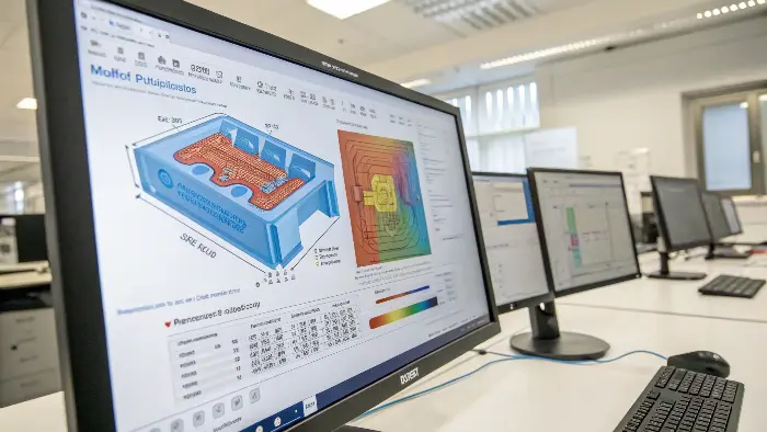
To really understand MFA, you need to see it as more than just a pretty picture. It’s a detailed simulation that breaks the molding process down into key stages. By looking at each stage, you can pinpoint exactly where and why a problem might occur. It’s a systematic way to debug your part before it even exists.
The Three Core Stages of Simulation
The analysis program does not analyze the process as a whole. It analyzes it step by step, just like the actual molding cycle. The three fundamental phases are filling, packing, and cooling.
-
Stage of Filling: It is the first and most basic step of the analysis. It simulates the molten plastic being injected and filling the open mold cavity. The software tells you if the part fills or you will have a "short shot." It also predicts the location of weld lines, where the two flow fronts meet, and air traps, where air pockets are trapped with no escape route.
-
Stage of Packing: Once the cavity is filled, the machine keeps applying pressure to pack more plastic into the mold. This is done to enable the material to shrink upon cooling. The packing analysis is necessary to prevent sink marks (small surface depressions) and voids (bubbles in the interior).
-
Cooling Stage: This may be the most critical stage for part quality. The simulation mimics the cooling and solidification of the part. Non-uniform cooling is the leading cause of warpage. The simulation helps you design the cooling channels of the mold in such a way that the part cools as uniformly as possible, minimizing internal stresses.
What the Software Needs to Work
The quality of input data is the sole determinant of an accurate simulation. This is one of the things I realized the hard way on one of my first projects. Our analysis had run perfectly, but the actual components were distorting terribly. It happened that we had applied the wrong thermal properties of the particular grade of polycarbonate that we were using. It was a typical garbage in, garbage out. You need to supply the software with correct data, such as a detailed 3D model of the part, the correct data on the plastic material you intend to use, and the proposed processing conditions such as injection speed and mold temperature to obtain a useful result.
Why Is Mold Flow Analysis So Important for Your Projects?
Are you experiencing surprise production delays and cost overruns because of mold rework? Each modification to a finished mold costs thousands of dollars and weeks of precious time, which generates enormous stress and pressure on you and your staff. You are constantly battling fires instead of designing and coming up with new ideas. Mold flow analysis is your preventive shield. It shifts problem-solving from the factory floor to the design screen, saving you a tremendous amount of money, time, and stress.
The benefit of mold flow analysis is that it prevents problems before they arise. It’s an insurance policy on costly manufacturing errors. By simulation, you can optimize for part and mold design, ensure manufacturability, and predict finished quality of the part. It reduces the necessity for costly and time-consuming mold changes, reduces product development time, and ultimately leads to a faster time-to-market with a better product. It’s a question of moving from a reactive to a proactive approach.
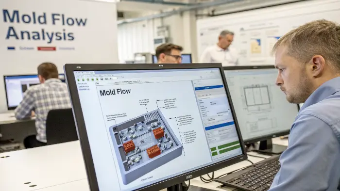
The benefits go far beyond just catching errors. Using MFA fundamentally changes how you approach part design. It encourages you to think about manufacturability from the very beginning. This proactive mindset leads to more robust designs, smoother production launches, and ultimately, a better final product. It’s about building quality in, not inspecting defects out.
The Financial and Time Savings
Now, real numbers. A consumer product injection mold can be easily $50,000 or more. So, now, you have run your first samples and discover that you have a significant warpage problem that renders the part unusable. This may need re-cutting of much of the steel mold. This rework would be 15,000 dollars and three to four weeks. In the meantime, your production line is out, and your product launch is postponed. I recall a project in which I was working on a housing of a medical device. The MFA report indicated a serious warpage problem because of a thick rib feature. The problem was solved by just modifying the rib shape and the gate position in the CAD model without cutting any steel. That minor adjustment saved our client about 25,000 dollars in mold changes and put their product on the market a month sooner. That is the physical strength of MFA.
Key Design Optimizations
Mold flow analysis is not just a system for finding red flags; it’s a powerful tool for optimization. It gives you the data you need to make informed decisions that improve every aspect of your part and mold design. It helps you answer critical questions like "Where is the best place to put the gate?" or "Is this wall thickness going to cause sink marks?"
Here’s a table that breaks down how MFA helps you optimize specific features:
| Feature to Optimize | How Mold Flow Analysis Helps | Result |
|---|---|---|
| Gate Location | Predicts the fill pattern, pressure, and weld line locations. | Optimal filling and reduced cosmetic defects. |
| Part Thickness | Identifies areas that are too thick (sink) or too thin (short shot). | More uniform wall thickness and stronger parts. |
| Cooling System | Analyzes temperature distribution and total cooling time. | Reduced cycle time and minimized warpage. |
| Runner System | Balances the plastic flow to multi-cavity molds. | Consistent, identical parts from every cavity. |
| Material Choice | Simulates how different materials will behave in the same mold. | Confidence in material selection before ordering. |
Mold Flow Analysis in the Future
With an increasingly large number of manufacturing divisions embracing digital transformation, mold flow analysis is growing in prominence as an essential designing tool for more efficient, more accurate, and more environmentally sustainable plastic parts. Traditionally used to predict how molten material would fill a mold, the technology is quickly evolving with the integration of artificial intelligence, cloud computing, and high-end simulation software.
The future potential of mold flow analysis is in real-time optimization, reduced material waste, faster prototyping, and more smart collaboration among manufacturers and engineers—a means whereby companies keep ahead while addressing growing demands for cost-efficiency and eco-friendliness during production
Integration with Industry 4.0:
As the injection molding industry embraces Industry 4.0 technologies, mold flow analysis is becoming more integrated with real-time data and smart manufacturing systems. This integration allows for continuous monitoring and adjustment of the molding process, leading to even greater efficiency and quality control.
Simulation Technological Advances:
The latest simulation technology is increasingly making mold flow analysis more precise and easy to use. The new algorithms, quicker processing, and the better visualization tools are helping the engineers make better choices and refine the designs with more accuracy.
What Key Parameters Does Mold Flow Analysis Actually Look At?
You appreciate the utility of mold flow analysis but have no clue what specific data it is analyzing. To the world in general, it is a black box where you feed it a design and get a response. Without the most critical parameters, you cannot have a productive discussion with the analyst regarding the analysis or properly interpret the results. You can lose critical information hidden in the report which can make or break your project. Let’s open up that black box and look at the underlying parameters that drive the simulation.
Mold flow analysis checks some critical parameters to forecast the molding result. The most important among them are fill time, injection pressure, melt temperature, cooling time, and shear rate. It also checks for the position of weld lines and air traps. Through the evaluation of these parameters, the software is able to anticipate some common problems such as incomplete filling (short shots), surface faults, and structural faults such as warpage. Knowledge of these parameters is important for the interpretation of the result and making the appropriate design decisions.
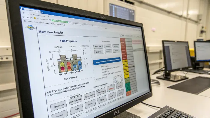
When you get an MFA report, it can be filled with dozens of plots and charts. It’s easy to get lost in the data. However, from my experience, you only need to focus on a few key outputs to get 90% of the value. Learning to read these core results will give you the confidence to guide your design decisions effectively.
Understanding the Filling Pattern
The first thing I always look at is the Fill Time plot. It is an animation displaying a color-coded map of the filling of the mold cavity by the plastic with time. The thing you want to see is a smooth, balanced and uniform advance of the flow front. When you notice areas that fill significantly later than others, that is a red flag of a so-called hesitation effect, which can lead to surface defects or structural weaknesses. This plot also makes clear to you where the various flow fronts will intersect. Your weld lines will be these meeting points. A weld line is a weak area, and the analysis assists you in changing the design, such as relocating the gate, to relocate these weld lines to less critical or less visible portions of the part.
Pressure, Temperature, and Warpage
Once the fill pattern has been checked, I examine the pressure and temperature maps. The Injection Pressure plot informs you of the amount of force required to fill the part. In case the pressure is too high, this may be a sign that the walls are too thin or the gate is too small. This is a clear indication that you should change the design. The plot of Temperature at Flow Front is also essential, as it indicates whether the plastic is cooling too fast prior to the fill being complete. However, the most potent output is the analysis of Warpage. It uses all of the cooling, pressure and material shrinkage data and forecasts the final, deformed shape of your part once it has been ejected out of the mold. It will literally tell you, in millimeters, how far the part is supposed to bend or twist. This information is invaluable to any component that has to fit another.
Is Analysis Always Necessary with any Application?
The short answer: no. The following details may provide some aid in determining if MFA is well-fitted in your application:.
TOLERANCE REQUIRE
Tight tolerances are an anathema to plastic injection mold designers anyway. Software that can analyze and demonstrate whether a product will meet spec prior to cutting a tool is a godsend.
PROJECT SCOPE
Obviously, the project would also need some monetary threshold that would render worthwhile the investment of funds/time, software, and skill in order to perform the experiments.
PRODUCT GEOMETRY
The more complicated the product shape, the more you will gain from MFA. Why? The more complicated the product shape is, the more unpredictable the flow is. Predicting how a basic mold shape would fill is much more straightforward
UNCOMMON MATERIAL
Engineers are well-versed in the fill patterns of average materials but others, more so materials that have fillers, need examination at the onset. Below is an MFA software tutorial video from SolidWorks that details how the software works and how the software will be beneficial in the design process. There are other MFA software providers available; you will desire the software that is best suited for the requirements of your project.
How Does Mold Flow Analysis Help Prevent Flow Marks?
You’ve designed a beautiful surface with a perfect, mirror-like finish in your CAD model, but the first molded prototypes are full of ugly flow marks, swirls, and blush. These visual imperfections can lead to product rejection, especially for consumer-exposed parts where looks are everything. It is extremely disappointing when a perfect functional part is rejected because it is not attractive. Mold flow analysis is your best diagnostic and prevention tool for these surface issues before they ever appear on a physical part.
Flow marks are blemishes on the surface resulting from changes in the rate of flow of the plastic and cooling while moving through the mold. Mold flow analysis eliminates them through computer modeling of the speed and temperature of the plastic. It can identify areas of sudden change in the rate of flow or where plastic is cooling rapidly. By evaluating these parameters, you can modify the gate design, injection speed, or wall thickness to provide for a smoother, more consistent flow, resulting in a perfect surface finish.
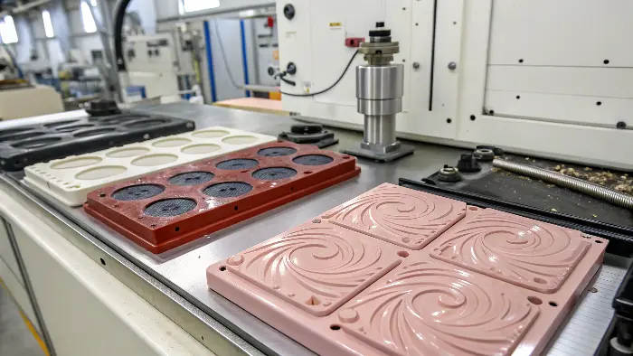
Dealing with cosmetic defects can feel like a guessing game. The machine operator might try adjusting temperatures or pressures, but it’s often just trial and error. MFA takes the guesswork out of the equation. It allows you to see the invisible—the behavior of the plastic inside the mold—so you can address the root cause of the problem directly in the design phase.
Diagnosing the Root Cause
Flow marks are not a single problem; they come in several forms. Understanding the type of defect is the first step to fixing it.
- Jetting: This occurs when plastic shoots straight into the cavity from the gate, creating a snake-like pattern on the surface. The MFA software can predict this by analyzing the velocity of the plastic. If the velocity plot shows a very high-speed stream entering the cavity, that’s a clear warning for jetting.
- Flow Lines or Blush: These often appear as a hazy or cloudy area near the gate. They are caused by the plastic cooling too rapidly as it tumbles into the cavity, leading to variations in the surface gloss. The temperature analysis in MFA can highlight this issue by showing a steep temperature drop right at the gate.
By simulating these conditions, MFA helps you diagnose the specific cause of the potential flow mark, whether it’s related to flow speed, temperature, or gate design.
Finding the Solution with Simulation
When the analysis has found a possible problem with flow marks, then it also becomes your virtual testing ground to find solutions. This is where MFA really excels. As an example, to correct the jetting issue I mentioned, one of the solutions is to point the gate towards a wall or a core pin. This causes the plastic flow to rupture and disperse in a smooth manner. This change can be modelled in your CAD software and the simulation can be re-run within a few hours to check whether it worked. You may experiment with reducing the injection rate or raising the mold temperature to correct flow lines. These process parameters are adjustable in the software and the effect on the result is immediately visible. This loop of testing and refinement is virtually infinite times quicker and less expensive than trial-and-error on a multi-ton steel mold on the factory floor.
Conclusion
Concisely, the mold flow analysis is a necessary requirement in contemporary injection molding. It converts it into an exact science, as opposed to an art of guesswork. You can save time, cut costs, and avoid the fatal flaws that can kill your project by simulating and optimizing your design before you cut steel. It allows you to produce better parts quicker, so it is a basic step in becoming a master of the art of molding and a success in this business.
