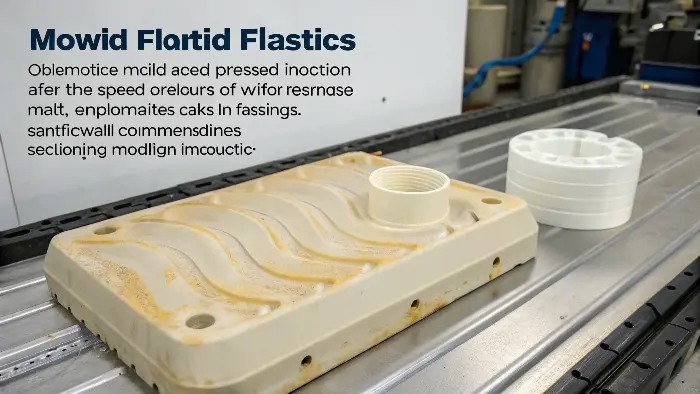
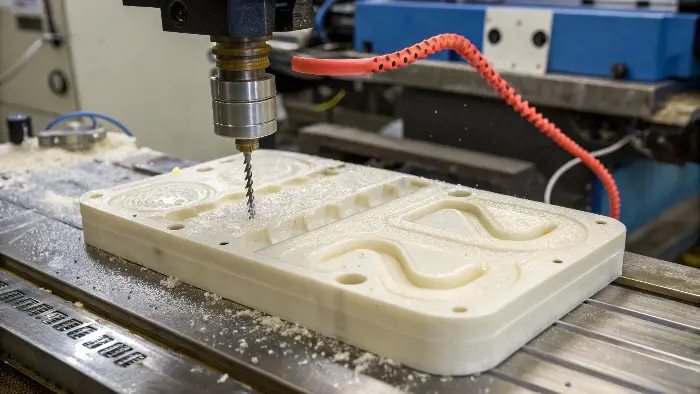
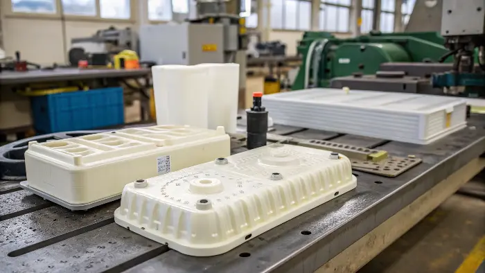
See wavy lines or discoloring streaks on your plastic components? These flow lines take away from the surface and even indicate weak spots, resulting in a huge headache and far too many scrapped parts. But imagine having smooth, imperfection-free surfaces by discovering and removing the causes.
To prevent flow lines, you will need to optimize your mold design with larger gates and runners. Also, increase the melt and mold temperature and the injection speed and pressure, and get it all just right. Make your part have an even wall thickness and use materials that have good flow properties. these steps enable the plastic to flow well, so these kinds of defects are less likely.

In our field, flow lines are a regular source of frustration. I’ve witnessed numerous projects where these ostensibly minor flaws resulted in significant expenses and delays. Addressing these concerns for customers became a crucial component of establishing trust when I first launched my own mold and CNC trade business. Fortunately, flow lines are frequently avoidable. We may greatly enhance part quality by rigorously examining our designs, procedures, and materials. Let’s investigate how.
How to reduce flow lines in injection molding?
Are flow lines consistently showing up on your injection molded parts, ruining them? This common problem can lead to rejected batches and unhappy customers, seriously affecting your productivity. But fear not, there are critical design and process changes that can greatly minimize these appearance defects.
To reduce flow lines, try to increase the nozzle, melt, and mold temperatures to enable the plastic to flow more freely. You can also raise the injection speed as well as pressure to pack the cavity more rapidly and more evenly. Position your gates correctly and make them big enough so the plastic will not cool too rapidly or get stuck. Venting correctly is also required.

Reducing flow lines frequently involves striking a balance between the behavior of the plastic and the construction of the mold. I recall an instance with a customer who made interior components for cars. Flow lines on a big, flat component tormented them. Before examining the mold, we spent a considerable amount of time adjusting settings on their machine. It turns out that a faster injection fill rate combined with a little higher melt temperature made a significant effect. Let’s divide up the areas that need attention.
Key Areas for Flow Line Reduction
To effectively reduce flow lines, we must take into account both the injection molding process parameters and the design of the mold itself.
-
Process Parameter Adjustments:
- Temperature Control:
- Melt Temperature: A higher temperature of the melted plastic reduces its viscosity (how runny it is). This makes it more smoothly flow into the mold. Just be careful not to heat it too much, as this will destroy the material.
- Mold Temperature: A hotter mold prevents the plastic from cooling too rapidly as it enters. It provides it with additional time to fill the cavity homogeneously before it solidifies.
- Nozzle Temperature: Regulate the nozzle temperature according to the melt temperature to prevent premature cooling at the inlet.
- Pressure and Speed:
- Injection Pressure: Higher pressure will be better suited to push the material into all areas of the mold more easily.
- Inj. Speed: Higher injection speed will maintain the melt front at the same temperature and flow more uniformly, thereby reducing the likelihood of flow lines caused by cooling variations. Too high, though, will create other issues like burning or jetting.
- Holding Pressure: Proper holding pressure keeps the part well-packed out, which will at times minimize the visibility of flow lines.
-
Design Considerations for Mold:
- Gate Design and Location:
- Gate Size: Narrow gates can restrict flow and cause the plastic to cool too fast, creating flow lines. Bigger gates normally eliminate the issue.
- Gate Location: The gate must be positioned so that the plastic can move in one direction if at all feasible, and preferably in thicker parts of the part first.
- Runner System: Similar to gates, runners that are too small or too large will cause more pressure drop and cooling. The sizes of runners must be optimized for symmetric flow.
- Wall Thickness: Abrupt variations in wall thickness will produce variations in flow velocity and rates of cooling, which produce flow lines. Attempt uniform wall thickness in the part. If variation cannot be avoided, use gradual variations.
- Venting: Trapped air inside the mold cavity may impede plastic flow and cause defects, including flow lines. Provide adequate vents in the correct location to allow air release as the plastic fills the mold. I have found many molds in which some carefully positioned vents eradicated persistent flow line problems.
| Parameter/Design Element | Adjustment to Reduce Flow Lines | Potential Trade-off/Caution |
|---|---|---|
| Melt Temperature | Increase | Material degradation if too high |
| Mold Temperature | Increase | Longer cycle times, potential for sinks |
| Injection Speed | Increase | Jetting, burning, flash if too high |
| Injection Pressure | Increase | Flash, mold wear if too high |
| Gate Size | Increase | Larger gate mark, longer de-gating time |
| Wall Thickness | Make uniform/gradual transitions | May conflict with part design needs |
| Venting | Add/Improve | Potential for flash if vents too large |
How to avoid jetting in injection molding?
Does the final product have unsightly, snake-like marks from your plastic occasionally shooting into the mold cavity like a jet stream? Known as "jetting," this condition can result in structurally unstable spots in addition to ruining the appearance. Fortunately, you can usually avoid it by making adjustments to your injection procedure and gate design.
Avoid jetting by immediately directing the flow of molten plastic into a core pin or a mold wall upon entering the cavity. This causes the jet to break apart. Moving the gate or redesigning it in a fan or tab style can also be effective. Reducing the initial injection speed might occasionally aid in the melt front creating a more steady flow.

I have frequently come across jetting, a particular kind of flow fault, particularly when working with high-viscosity materials or improperly positioned gates. It occurs when high-velocity injections of molten plastic are made through a gate and into an open, unobstructed hollow section. The material "snakes" its way across the mold surface rather than filling it in smoothly and gradually. Let’s examine ways to put an end to this.
Strategies to Prevent Jetting
Prevention of jetting mostly depends on the control of how the material enters the mold cavity and starts filling it.
-
Understanding Jetting:
- The fundamental issue is the high-speed stream of plastic lacking a surface to flow against or along initially. This causes it to jet across the cavity, premature chill where it impacts the mold surface, and subsequently get shoved about by subsequent material flow, thereby creating the typical jetting pattern.
-
Gate Design and Location Solutions:
- Gate Positioning: This is generally the preferred method. Position the gate so that incoming stream of plastic strikes an obstacle straight ahead, e.g., the opposite cavity wall or a core pin. This "breaks" the jet and forces the material to enter more uniformly.
- I recall one project on a consumer electronics box where jetting was a critical issue near a small pin gate. We shifted the gate slightly so the plastic first hit a nearby rib feature. The jetting disappeared completely.
- Gate Type:
- Tab Gate: A tab gate has a thin, small tab on the portion at the gate location. Plastic flows into the tab through the gate and from the tab into the main cavity. It retards and spreads the flow front.
- Fan Gate: The fan gate is wider at the entrance to the cavity and narrower towards the runner. It helps distribute the flow of plastic as it enters the cavity, reducing the jetting effect, especially for wide, flat components.
- Submarine (Sub) Gate / Tunnel Gate: While often used for de-gating autos, their sloping entryway will occasionally be capable of being positioned to deflect flow against a cavity wall, although they can also cause jetting unless properly designed for a specific part geometry.
-
Process Adjustments:
- Injection Speed Profile: Instead of a single rapid injection speed, use a customized injection. Start with a slower speed as the material passes through the gate and just starts to fill the cavity. Once a stable flow front is established, the speed can be increased to fill the rest of the part. Many modern machines permit for exact control over the injection speed profile.
- Melt Temperature: A slightly higher melt temperature can decrease density, making the plastic flow a bit more easily, which can occasionally help reduce jetting tendencies, but this is usually a temporary solution to gate layout.
| Solution Type | Specific Action | How it Prevents Jetting |
|---|---|---|
| Gate Location | Aim flow at cavity wall or core pin | Breaks the direct stream, promotes even flow front |
| Gate Design | Use Tab Gate | Slows and spreads flow before entering main cavity |
| Gate Design | Use Fan Gate | Spreads flow widely at entry, reducing focused jet |
| Process Control | Profiled Injection Speed (slower at start) | Allows stable flow front to establish before high-speed fill |
| Material Property | Increase Melt Temperature (cautiously) | Reduces viscosity, potentially smoother initial flow |
By carefully balancing these gate and process tactics, you may successfully reduce jetting and provide parts with both high aesthetics and structural integrity.
What Causes Flow Lines in Injection Molding?
Mold Design
Mold design is key to the plastic manufacturing process. A poorly designed mold will increase production costs due to sub-optimal plastic flow within the mold. You’ll see lines and defects in the finished product.
Flow lines will occur as the molten plastic moves past the thinner areas to fill the thicker regions. You’ll see this because the thinner parts of the mold have cooled and become gummy.
Cooling Rates
Cooling rate of the molded plastic is a critical factor in flow lines. If plastic cools too fast it will cause uneven patterns and weak points in the part. If plastic cools too slow it will cause warping and deformation of the part shape.
Injection Speed
In injection molding flow lines will occur if injection speed is too slow. The molten plastic will start to cool before the mold cavity is filled. To avoid this manufacturers must ensure they use the right injection speed for their process.
How to fix flow lines?
Are you wondering if parts with flow lines that have already been made may be saved or if the issue can be promptly fixed during production? The wisest course of action is usually to avoid flow lines from the beginning, but occasionally you need to find solutions for problems that already exist. Fortunately, there are strategies to deal with them.
Changing process parameters, such as raising the injection speed or melt/mold temperature, is frequently the first step in fixing existing flow lines. Mold adjustments such widening gates or runners, enhancing ventilation, or moving gates may be required if these short-term solutions prove ineffective. Sometimes the solution is to switch to a material with better flow characteristics.

Adjusting the machine settings is frequently the first inclination when flow lines occur. Since process changes are typically the quickest and least expensive solutions, this is a reasonable place to start. I’ve worked alongside operators on molding machines for many hours, carefully modifying settings to eliminate these flaws. It’s time to examine the material or the mold if it doesn’t work.
Troubleshooting and Fixing Flow Lines
Here’s a more structured approach to fixing flow lines, moving from simpler to more involved solutions:
-
On-the-Machine Process Adjustments (The First Line of Defense):
- Increase Melt Temperature: Higher temperature reduces viscosity, improving flow. Incrementally increase within the material’s recommended range.
- Increase Mold Temperature: A warmer mold surface prevents premature freezing of the plastic flow front.
- Increase Injection Speed: Faster filling can help maintain melt temperature and achieve a more uniform flow front.
- Increase Injection Pressure/Holding Pressure: Ensures the cavity is fully packed and can sometimes help push flow lines out or make them less visible.
- Check Nozzle Temperature: Ensure it’s not too low, causing premature cooling.
- Verify Dryer Performance: If using hygroscopic materials (like Nylon, PC, PET), ensure they are properly dried. Excess moisture can cause splay marks, which can sometimes be confused with flow lines or exacerbate them.
-
Mold-Related Checks and Modifications (When Process Changes Aren’t Enough):
- Check Vents: Clogged or inadequate vents are a common culprit. Clean existing vents and consider adding more, especially at the end of flow paths or in areas where air can get trapped.
- Gate and Runner Inspection/Modification:
- Enlarge Gates/Runners: If they are too restrictive, they can cause excessive pressure drop and premature cooling.
- Relocate Gate: Sometimes, changing where the plastic enters the cavity can drastically alter the flow pattern and eliminate lines. This is a more significant modification.
- Radius Sharp Corners: Sharp corners in runners or gates can disrupt flow. Adding radii can smooth the path.
- Mold Surface Polish: A highly polished cavity surface can sometimes reduce the visibility of flow lines, though it doesn’t address the root cause of uneven flow.
- Consistent Wall Thickness: If the part design has significant variations in wall thickness, this is a prime cause. While hard to "fix" without a part redesign, sometimes mold modifications can help manage the flow into these sections better.
-
Material Considerations:
- Switch to a Higher MFI Material: A material with a higher Melt Flow Index (MFI) or Melt Flow Rate (MFR) will flow more easily at a given temperature and pressure.
- Add Processing Aids/Lubricants: Certain additives can improve the flow characteristics of the plastic, but these must be compatible with the base resin and the end-use application.
| Troubleshooting Area | Action | Expected Outcome for Flow Lines |
|---|---|---|
| Process | Increase Melt/Mold Temperature | Improved flow, reduced viscosity |
| Increase Injection Speed/Pressure | Faster, more uniform fill | |
| Check Material Drying | Eliminate moisture-related issues | |
| Mold | Clean/Add Vents | Easier air escape, better fill |
| Enlarge/Relocate Gate; Optimize Runners | Less restricted, smoother flow | |
| Polish Cavity | Reduced visibility (cosmetic) | |
| Material | Use Higher MFI Grade | Easier flow |
| Consider Flow Enhancing Additives | Improved processability |
The process of repairing flow lines is iterative. If required, proceed to more complicated solutions (mold alterations or material changes) after making the simplest and least expensive adjustments (process parameters).
Selecting Materials to Improve Resin Flow
Each plastic behaves differently in the injection molding process. Those with lower melt temps and lower viscosity like polyethylene and polypropylene flow easily and will fill a mold more smoothly and evenly.
Others like polycarbonates are sticky and would be a bad choice for thin parts because they are hard to get to fill a mold. ABS thermoplastics are in the middle and work for some applications.
Plastics aren’t interchangeable. Some parts need to be strong or flexible and others may need impact or chemical resistance. With so many plastics to choose from today, another material in the same family with a better melt flow or viscosity may be an option to avoid flow lines and make a better part.
Conclusion
Injection molding flow line prevention essentially boils down to meticulous mold design, accurate process control, and astute material selection. You can reliably create high-quality, flawless pieces by ensuring that the molten plastic flows uniformly and stays at the proper temperature. In the long term, this not only looks nicer but also saves a significant amount of time and money.
