Frustrating bubbles in your plastic parts are also a common issue that can compromise the appearance, weaken the construction, and lead to costly rejections and material waste. You know there is a solution, but you find it very difficult to nail down what the problem is, like second-guessing. I want to demonstrate to you some systematic steps that you can take to have them out of your life forever.
Injection molding in parts can have bubbles caused by many different reasons. To solve these problems begin at the most likely causes. The first thing is to make your plastic resin dry, which means you have to check your drying system and adhere to the particular instructions of your material. Then set your machine. An attempt should be made to reduce the barrel temperature to avoid overheating and degrading of plastics. Also, lower injection velocity so that trapped air could make its way out via the mold vents. Lastly, back pressure can be ramped up to a level such that a denser melt can be formed, expelling any existing gas bubbles.
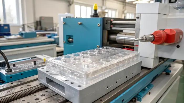
As you have the direct action steps in front of you, you are making a good step in the right direction. However, mastering this and ensuring that it will not occur again requires that you know just what is happening within your machine and your mold. So, now we are going to dig deep into the kinds of bubbles and how exactly those can be corrected so that you will be able to solve the problems effectively. Such understanding will not only save you time and resources in the long term.
What are the bubble marks in injection molding?
Have you ever seen a bubble in a part and thought to yourself what does it consist? You may think that all bubbles are equal but by diagnosing the problem wrongly, you may end up on a wrong track thus spending your time in solutions that are not effective. You have to identify it well to know the problem in order to solve them. Now what are these marks? Let us clear that up.
Injection molding bubble marks are holes entrenched in the plastic. They are of two types: there are gas bubbles and vacuum voids. The moisture, trapped air, or the gases which are extracted due to overheated plastic cause gas bubbles. They tend to be circular and may come in any location. Shrinkage gives rise to vacuum voids. They are a result of cooling the outside of the section too quickly which causes the molten core to tear apart when it enshrinks leaving a vacancy. The first step in repair is locating which of them you have.
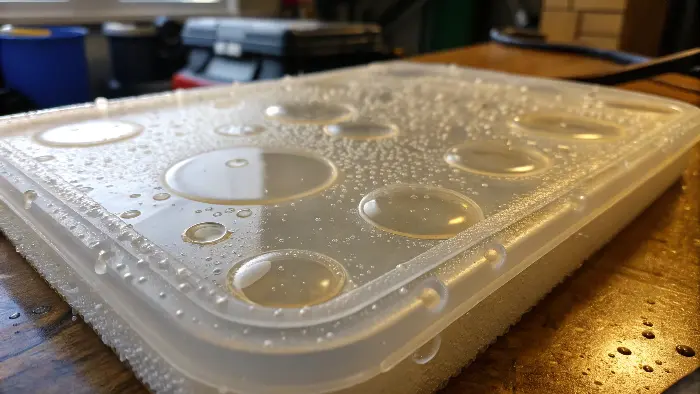
The most important step in troubleshooting is the realization of the distinction between these two defects. I watched teams spend days dialing up and down pressures when it really needed damping of the material. Or they will will waste hours of drying resin when the problem is in fact part design leading to shrinking. With that said, let us simplify this so you can be able to tell them apart like an expert.
Gas Bubbles vs. Vacuum Voids: How to Tell the Difference?
A simple test will enable one to differentiate between them easily. Carefully using a heat gun, warm the part of the part where the bubble is located. A gas bubble is filled with pressurized gas and therefore when the plastic softens, there is likelihood that the bubble would either expand or migrate. Keep in mind that a vacuum void is a vacuum and in most cases, will normally collapse and vanish when the surrounding plastic melts and fills the gap available.
The other means is through location. Gas bubbles are not excluded in any place and tend to move towards the last to fill regions. Vacuum voids nearly always are right in the middle of the thickest portions of a piece, where it takes the longest to cool.
Here is a simple table to help you remember the key differences:
| Feature | Gas Bubble | Vacuum Void |
|---|---|---|
| Cause | Moisture, trapped air, material degradation | Material shrinkage during cooling |
| Shape | Usually spherical or slightly elongated | Irregular, follows the internal melt flow |
| Location | Can be anywhere, often near the end of fill | Almost always in the thickest sections |
| Appearance | Often shiny, like a bubble in water | Can be a cloudy or empty-looking spot |
| Heat Test | Expands or moves when heated | Collapses and disappears when heated |
Common Causes of Gas Bubbles
After you’ve determined that you do indeed have gas bubbles, your issue will be threefold: water, air, and heat.
- Moisture: The majority of plastics, including Nylon, Polycarbonate (PC), and ABS, are "hygroscopic," or they will absorb moisture from the air. When these wet pellets go into the hot barrel, the water instantly boils off and creates bubbles that get delivered into your part. That’s why drying material is not a choice.
- Trapped Air: Air is always trapped in the mold cavity prior to injection. If it is unable to escape quick enough, the molten plastic will capture it. This is a mold venting problem.
- Material Degradation: If your barrel temperature is too high or if the plastic is too long in the barrel (residence time), it will degrade. This chemical process creates gases, which become bubbles in your part.
Now that you understand the underlying causes, you can move from merely "seeing bubbles" to knowing where the answer is.
Difference Between Voids in Vacuum and Bubbles
Bubble:
A simple heat test can be performed to determine the difference between vacuum voids and gas pockets. If the area is heated and the wall stock collapses, revealing a sink, it’s likely a vacuum void. If heating causes the area to inflate or expand, it’s likely a gas pocket. Voids in injection molded parts can significantly impact both the quality and performance of the final product.
Effect on Voids in Plastic Components
Plastic parts produced by injection molding and the like may form interior voids when the plastic contracts during the cooling down or has air inclusions during the molding procedure. Interior voids in molded parts may induce many undesirable effects as follows.
Appearance Defects
In clear parts, voids will manifest as seen air pockets, which may not look good and impact the visual quality of the part. In colored or opaque parts, the voids will not be seen on the outside but will still impact the integrity of the part.
Voids can cause the formation of surface irregularities, which would not be desirable for high-grade or critical applications.
Structural Weakness
Voids introduce points of weakness in the part, since the fact that there are air pockets results in less material to handle loads. This will lower the part’s mechanical strengh and durability considerably.
Components with voids are most likely to fail when stressed, which results in the possibility of breaking or malfunctioning when used.
Functional Defects
In functional parts, the voids will cause disruption to the part’s functionality during its operation, hence performance problems. In parts that are required for pressure or mechanical loads, the parts will fail early due to the presence of the voids. The voids have the capability to cause dimensional inaccuracy, an element vital for tight-tolerance jobs. This could lead to part assembling problems or misfit among parts.
How to get rid of bubbles in injection?
You have diagnosed the defect as a gas bubble, and have assured yourself your material is not slighly moist. But the bubbles remain. This is the time to be frustrated and it points at your injection process settings. At times it seems you are simply fiddling with knobs but there is quite a logic behind it. Let us deal with specific machine settings which will dispel those bubbles.
To remove bubbles caused during the process of injection, attention should be paid to regulating melt flow and pressure. Initially, slow the speed of injection; this gives the air in the mold cavity greater chance to drift out of it through the openings. Then raise the back pressure. This lumps the plastic up during screw recovery forcing the entrapped air and volatiles out of the plastic before the shot can actually be injected. Also, you should look at your decompression (suck-back) value as this might cause air to be drawn into the nozzle tip.
I recall once when a project that I was working on involved a transparent polycarbonate piece. Days we had it out with bubbles. It was dry as a bone and the molds perfect. The issue was so minute. The operator had correctly adjusted the suck-back a few millimeters low so the nozzle drooled. We decreased by only 2mm and the bubbles disappeared fast. In some cases, smaller setting means difference at its grandest. So, how to master these parameters? Let us go into it.
Optimizing Injection Speed and Pressure
Think of injection speed as pouring water into a bottle with a narrow neck. If you pour too fast, the air can’t get out, and the water splashes and traps air bubbles. The same thing happens inside your mold. A very high injection speed can create turbulence and trap air before it can reach the vents.
- Start by reducing the overall injection speed by 10-20% and see if it helps.
- Consider injection profiling. Instead of one constant speed, you can program multiple stages.
A common strategy is to start slow to let the air in front of the melt front escape, then speed up to fill the main body of the part, and finally slow down again at the very end to prevent flashing and allow the final pockets of air to vent.
The Critical Role of Back Pressure and Decompression
Back pressure is one of the most powerful, yet often misunderstood, settings for bubble prevention. It’s the pressure applied to the front of the screw as it rotates and retracts to pick up the next shot of plastic.
- How it Works: Increasing back pressure forces the plastic pellets to be mixed and compressed more intensely. This creates a more uniform melt density and temperature. Most importantly, it squeezes out any trapped air or moisture that wasn’t removed by the dryer.
- What to Do:Increase the back pressure gradually from a low starting point (about 50–100 psi). As volatiles are driven out, you will frequently hear a hissing sound close to the feed neck. Take caution because excessive back pressure can raise shear heat and perhaps cause material degradation, which would put you back where you started.
Decompression, or suck-back, is when the screw pulls back slightly after picking up a shot. This is done to relieve pressure in the nozzle and prevent drooling. However, if it pulls back too far, it can suck air in through the nozzle opening, which then gets injected with the next shot. If you suspect this, try reducing the decompression distance to the bare minimum needed to control drool.
How to get rid of bubbles in the mold?
Suppose your material is dry and your injection process is behaving in a most ideal manner but those recalcitrant bubbles will not disappear? It is during this time when you have to quit staring at the machine and begin to stare at the tool itself. It is where you put it that is the problem, not what you put in. It might be the mold design, which gets trapped air or shrinkage dents.
Once bubbles have been formed by the mold, a bad vent or bad part design causing this is nearly always the reason. Be sure your mold is well vented at the final fill position and deep ribs in which trapped air can escape. This may create vacuum voids in case the part has very thick parts adjacent to thin ones. Redesigning the part so that the wall thickness is more uniform or core out thick areas will lead to the best solution.
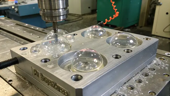
Here the skills of a good mold designer will shine forth. The mold designed well anticipates these problems. One of my consultancies was over a company producing a handle which was thick walled. They were beset by emptiness in the middle. They attempted everything with the process. The problem was solved not in the machine but in the CAD file. We coined out the back of the handle so there was even 3mm wall thickness all around. The empty spaces magically vanished and the component was even more lightweight and powerful.
The Critical Importance of Mold Venting
Every time you inject plastic into a mold, you are also compressing the air that was already inside. That air has to go somewhere. Vents are very shallow channels (typically 0.01-0.03mm deep) cut into the parting line of the mold that are big enough for air to escape but too small for the molten plastic to flow through.
- Where to Vent: Vents are most critical at the very last point the plastic reaches, often called the "end of fill." They are also needed anywhere air can be trapped, like at the top of tall ribs or bosses.
- Signs of Poor Venting: If you see bubbles, especially near the end of fill, it’s a huge red flag for poor venting. Other signs include burn marks (dieseling), where the trapped air gets so compressed it heats up and scorches the plastic, and short shots, where the trapped air pressure prevents the mold from filling completely.
- Fixing Vents: Vents can get clogged with residue over time, so the first step is to clean them. If they are too small or not in the right place, a toolmaker will need to add or enlarge them.
Designing for Uniform Wall Thickness
That is the cardinal principle of plastic part design, and the first, and greatest, protection against vacuum bubbles. Plastic cools in an exterior to interior manner. Should your section be very thick the outer walls will be solid before the center is really hot. When it is at full liquid state, this molten core eventually cools and shrinks hence attempts to inhale even more plastic to balance. But the gates or the environs of walls may be alread frozen it cannot. Thus, it disintegrates itself forming vacuum void.
- The Goal: Aim for a wall thickness that is as uniform as possible throughout the part. A good rule of thumb is to keep variations within 25%.
- Solutions:
- Coring Out: Instead of a solid thick section, can you hollow it out from the back, leaving a uniform wall? This is the most common solution.
- Ribs: Instead of a thick section for strength, can you use a thinner nominal wall and add reinforcing ribs?
- Gas-Assist Molding: For parts where thick sections are unavoidable, this advanced process injects nitrogen gas into the molten core, which pushes the plastic against the mold walls and compensates for shrinkage, eliminating voids.
By addressing issues in the mold itself, you are fixing the problem at its source, leading to a much more stable and repeatable process.
How to fix bubbles in injection molding?
You have learned what the various kinds of bubbles are and the material, process, and mold-specific causes. When you stand before the machine with a faulty part in your hand though, you need to take action. And switching between various fixes without a logical reasoning may turn things for the worse. This is a checklist that you can follow in three simple steps any time this problem presents itself to you.
The following should be a four-step process in pinpointing bubbles in injection molding. The first thing to do is to determine the defect: it is a gas bubble or a vacuum void? Second, inspect your material handling with a moist and dry condition of the plastic as the manufacture specifies. Third, change your process parameters that are skewed towards temperature, speed and pressures. Fourth, when troubleshooting, look at mold to see whether it is vented and designed properly when the problem continues. This chain of logic makes you identify the root cause effectively.
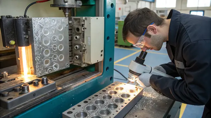
Imagine yourself at a crime scene as a detective. You don’t just start making arrests at random. After determining the crime, you search for hints, speak with witnesses, and gradually reduce the number of potential suspects. Molding issues may be resolved efficiently and successfully using this methodical technique, which will save your business money and time. Let’s go over the checklist together.
Step 1: Identify the Defect
Before you touch a single setting, figure out what you’re dealing with.
- Is it a Gas Bubble? Look for round, shiny pockets that can be anywhere in the part. If you heat it, it will likely expand. If yes, your problem is related to moisture, trapped air, or material degradation.
- Is it a Vacuum Void? Look for irregular, empty-looking spots in the thickest sections of the part. If you heat it, it will likely collapse. If yes, your problem is related to shrinkage and part/mold design.
Step 2: Check the Material
This is the most common cause of gas bubbles. Don’t skip this step.
- Verify Drying: Is the material hygroscopic (e.g., PC, Nylon, ABS, PET)? Check the manufacturer’s data sheet for the recommended drying time and temperature.
- Check the Dryer: Is your dryer actually working? Check the airflow, temperature, and dew point to ensure it’s performing correctly. I’ve seen many cases where the dryer was on, but not functioning properly.
Step 3: Adjust the Process Parameters
If the material is perfect, move to the machine settings. Use this table as your guide. The right adjustment depends on the defect you identified in Step 1.
| Parameter | Adjustment for Gas Bubbles | Adjustment for Vacuum Voids | Why it Works |
|---|---|---|---|
| Barrel Temperature | Lower | Lower (if causing degradation) | Prevents material from breaking down and releasing gas. |
| Injection Speed | Lower | Lower (to reduce shear heat) | Gives trapped air time to escape through vents. |
| Back Pressure | Increase | Increase | Creates a denser, more uniform melt, forcing out volatiles. |
| Holding Pressure | N/A | Increase and extend time | Packs more material into the mold to compensate for shrinkage. |
| Mold Temperature | Increase | Decrease (carefully) | A hotter mold keeps the plastic molten longer, allowing gas to escape. A cooler mold helps the part set up faster, but can trap stress if not balanced with holding pressure. |
Step 4: Inspect the Mold
If you’ve tried everything above and the bubbles are still there, the problem is almost certainly the tool itself.
- Check Vents: Are they clean? Are they in the right places (especially end-of-fill)? Are they large enough?
- Check Part Design: Is the wall thickness uniform? If you have vacuum voids in a thick section, the part likely needs to be redesigned to core out that area.
By following this checklist every time, you will solve the problem faster and learn more about your process with each experience.
Conclusion
Removing bubbles in your injection molded parts does not need to be such a secret. It is logical deduction. You can exhaust your quest by filtering first the kind of bubble. Then: work through the possibilities in a logical order: first material, then process parameters, and lastly the mold itself. This step-by-step guideline will help you become a more competent and fearless trouble-shooter and that eventually you will display nothing but high quality and bubble-free parts.
