Are your plastic parts consistently out of spec? Incorrect shrinkage calculations1 often cause these expensive problems. This leads to frustration, delays, and wasted material for product designers like Jacky.
Mastering shrinkage involves understanding material behavior, using correct formulas for mold scaling, and applying practical compensation techniques during mold design2. This guide breaks down these steps for precise and predictable outcomes in your projects.
Understanding plastic shrinkage is absolutely fundamental in the world of injection molding. I’ve seen countless projects, from simple enclosures to complex automotive components, succeed or fail based on how well shrinkage was handled. It’s not just a theoretical number; it directly impacts the fit, form, and function of the final product. Getting it right means happy clients and profitable production runs. Let’s dive into how you, like Jacky, can get a better grip on this critical aspect of mold and part design, so your projects run smoother from the start.
How Do You Actually Calculate Shrinkage in Injection Molding?
Feeling lost when trying to predict how much a plastic part will shrink? Using a generic guess often means your parts won’t fit, leading to costly mold reworks and delays. You need a reliable way to figure this out.
To calculate shrinkage, you primarily use the material supplier’s shrinkage rate (S) and your desired part dimension (Lp). The basic formula for the mold cavity dimension (Lm) is Lm = Lp / (1 – S). For complex parts, detailed analysis or simulation is better.
Calculating shrinkage is a core skill for anyone in mold design or plastic part development. It starts with a fundamental understanding and a bit of math. The most common formula I rely on is Lm = Lp / (1 - S). Here, Lm is the dimension we need to make the mold cavity. Lp is the final dimension you want for your plastic part. S is the shrinkage rate of the specific plastic material you’re using, expressed as a decimal (so 2% becomes 0.02). For example, if Jacky needs a part feature to be 100mm long (Lp) and the material shrinks 2% (S), the mold cavity for that feature needs to be 100mm / (1 - 0.02) = 102.04mm.You’ll find the shrinkage rate S on the material datasheet from your resin supplier. Always look for the specific grade of material. A general Polypropylene will shrink differently than a Polypropylene with 30% glass fiber. Amorphous plastics like ABS or PC tend to shrink less and more uniformly. Semi-crystalline plastics like Nylon or PP usually shrink more, and their shrinkage can vary more with processing conditions. It’s also vital to understand that many factors influence this rate. |
Factor Influencing Shrinkage | General Effect |
|---|---|---|
| Material Type | Semi-crystalline (PE, PP, Nylon) shrinks more than amorphous (ABS, PC, PS). | |
| Fillers (e.g., Glass) | Usually reduces overall shrinkage but can make it directional (anisotropic). | |
| Wall Thickness | Thicker sections tend to shrink more and for a longer time. | |
| Mold Temperature | A hotter mold often allows more complete shrinkage to occur inside the mold. | |
| Melt Temperature | Higher melt temperature can lead to increased shrinkage. | |
| Packing Pressure & Time | Higher, longer packing generally reduces net shrinkage by adding more material. | |
| Gate Size & Location | Affects how well packing pressure is transmitted into the part. |
If you’re using fiber-filled materials, expect differential shrinkage. The part will shrink less in the direction of material flow and more across the flow. This is a major cause of warpage. [Personal story about a part warping due to unexpected differential shrinkage and how it was solved]. For very complex parts or when precision is paramount, simulation software like Moldflow becomes an invaluable tool. It can predict flow patterns and these complex shrinkage behaviors much better than simple formulas.
What Steps Are Crucial for Compensating for Shrinkage When Molding Parts?
Calculated the shrinkage, but unsure how to apply it to your mold design effectively? Just making the whole mold bigger by one percentage might not work for complex parts or tight tolerances, leading to dimensional errors.
Compensation involves scaling up the CAD model3 of the part by the calculated shrinkage rate(s) to create the mold cavity geometry. Designers often build molds "steel safe4," allowing for easier adjustments after initial trials if needed.

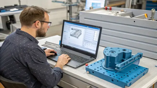
Once you have your shrinkage rate, the next step is to apply this to the actual mold design. This is where theory meets the toolmaker’s craft. Most 3D CAD systems have a scaling feature. I take the nominal part model that Jacky designed and scale it up. If the shrinkage is, say, 1.5% (or 0.015), I’d scale the part model by a factor of 1 / (1 - 0.015), which is approximately 1.0152. This enlarged model then becomes the target for machining the mold cavity.
For simple parts made from unfilled plastics, a single, uniform scale factor applied in all directions (X, Y, Z) might be okay. But for many engineering parts, especially those using filled materials or having complex geometries, we need non-uniform scaling. This means applying different shrinkage rates in different directions. I remember a long, thin electronics housing we did for a client. It was made of glass-filled polycarbonate. We had to apply a lower shrinkage value along its length (direction of flow) and a higher value across its width. Using an average would have distorted the mounting bosses.
We also almost always design "steel safe." This means if there’s any uncertainty, we make the mold cavity slightly smaller than the scaled-up calculation suggests. This results in the first sample parts (T1 parts) being slightly larger than the final desired dimension. Why? Because it’s much easier and cheaper to remove a tiny bit of steel from the mold to make the part smaller than it is to add steel if the part comes out too small. Adding steel often involves welding and re-machining, which is time-consuming and can compromise the mold. [Brief personal story about a time steel safe design saved a project]. For very critical dimensions or features prone to wear, using separate mold inserts is a smart strategy. If an adjustment is needed, we only need to remake or modify a small, less expensive insert instead of the entire mold block.
How Can You Accurately Measure Part Shrinkage After Molding?
Your first parts are molded, but how do you know if your shrinkage calculations were correct? Guessing or just visually checking parts isn’t good enough for quality control or for making informed decisions about mold adjustments.
Measure part shrinkage by comparing the dimensions of cooled, stabilized molded parts against the original nominal part design specifications or the mold cavity dimensions. Use precision tools like calipers, micrometers, or CMMs for accurate data.

After the mold is built and the first trial shots (T1 samples) are produced, we need to measure the actual parts very carefully. This is a critical feedback loop. It tells us how much the plastic actually shrank under real molding conditions. We compare these measurements to the original part print dimensions that Jacky specified.
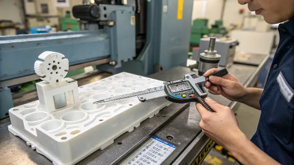
The main tools for this are precision measuring instruments. For straightforward dimensions, digital calipers and micrometers work well. For more complex geometries, contoured surfaces, or very tight tolerances, a Coordinate Measuring Machine (CMM) is essential. CMMs can measure points in 3D space with very high accuracy. Optical scanners are also becoming more common as they can capture the entire surface geometry quickly.
When we measure, we focus on critical dimensions defined on the part drawing. It’s important to let the parts cool down completely and stabilize to room temperature before measuring. Some materials, like Nylon, will also absorb moisture and change dimensions slightly over time, so for those, we might measure them after a specific conditioning period or straight off the machine and then again later.
The actual shrinkage (S_actual) can then be calculated using the formula: S_actual = (Dimension_mold - Dimension_part_measured) / Dimension_mold. So, if a mold cavity dimension was 102.0mm and the corresponding measured part dimension is 100.0mm, the actual shrinkage is (102.0 - 100.0) / 102.0 = 2.0 / 102.0 = 0.0196 or 1.96%. This measured shrinkage is then compared to the shrinkage value initially used for the mold design. If there’s a significant difference, and the parts are out of tolerance, adjustments to the mold (if designed steel safe) or the process parameters will be needed. I always insist on measuring a good number of parts, say 5 to 10, from different cavities if it’s a multi-cavity mold, to get a reliable average and understand consistency.
Beyond Shrinkage, What Other Injection Molding Calculations Impact Part Accuracy?
Is focusing only on shrinkage calculation enough for perfect parts? While crucial, shrinkage is just one piece of the puzzle. Other process calculations and settings directly influence if your parts meet their final dimensional targets.
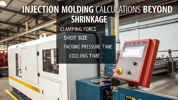
Beyond mold shrinkage, accurately setting molding machine parameters like clamping force, shot size, packing pressure and time, and cooling time is vital. These "calculations" or settings ensure the molding process itself supports dimensional stability and part quality.

While calculating shrinkage is for the mold design phase, several other "calculations" or critical settings in the molding process phase directly impact the final part dimensions and quality. Getting these right ensures the mold, which was designed with shrinkage in mind, can actually produce good parts.
First, clamping force. The machine must provide enough force to keep the mold halves tightly shut against the high pressures of molten plastic injection. We calculate the required clamping force based on the part’s projected area and the average cavity pressure for the material. Insufficient force leads to flash (plastic leaking out at the parting line), which definitely affects dimensions.
Next is shot size. This is the volume of plastic injected. It needs to be calculated to fill the part, the runner system, and leave a small cushion for the packing phase. If the shot size is too small, you get short shots (incomplete parts).
Then, packing pressure and time are extremely important. After the mold is mostly full, packing pressure pushes more material into the cavity to compensate for the volume reduction as the plastic cools and shrinks. The amount of pressure and how long it’s applied are critical. These are often fine-tuned during trials, but initial settings can be estimated based on material properties, part volume, and gate size. Proper packing minimizes sinks and voids. Gate freeze-off time is a key related factor; packing must continue until the gate solidifies.
Finally, cooling time. The part needs to cool sufficiently in the mold to become rigid enough for ejection without distortion. Cooling time can be estimated based on the thickest wall section of the part and the material’s thermal properties. Too short a cooling time can lead to warpage or inconsistent post-mold shrinkage. [Brief story about a part that warped because cooling time was too short].
All these parameters interact. Experienced process engineers often use Design of Experiments (DOE) to find the optimal process window where all these settings work together to produce consistent, dimensionally accurate parts as intended by Jacky’s original design and our shrinkage-compensated mold.
Conclusion
Mastering injection mold shrinkage involves precise calculation for mold design and careful control of molding parameters. This ensures parts meet specs, reducing waste and improving project success for designers like Jacky and manufacturers alike.
-
Learning about shrinkage calculations can prevent costly errors and improve the efficiency of your production process. ↩
-
Exploring mold design techniques can help you optimize shrinkage calculations, leading to better product outcomes and reduced waste. ↩
-
Scaling a CAD model correctly is essential for creating precise mold cavities, which directly impacts the quality of the final product. ↩
-
Learning about ‘steel safe’ practices can help you design molds that are easier to adjust, improving efficiency and reducing waste. ↩
