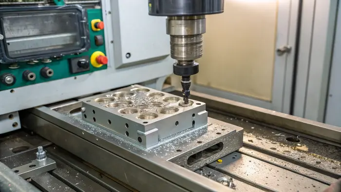
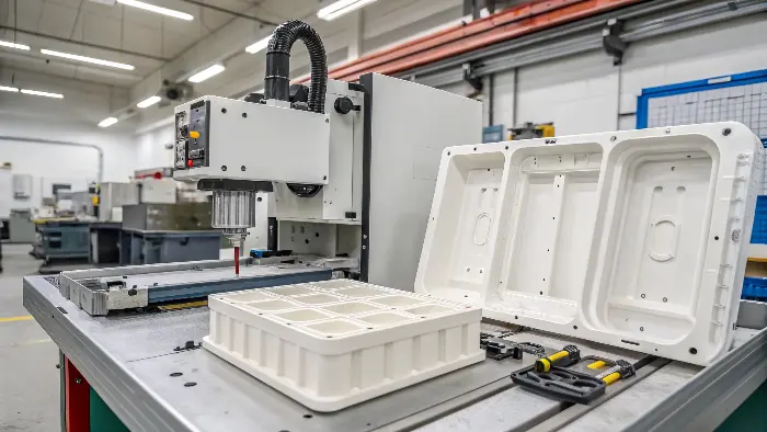
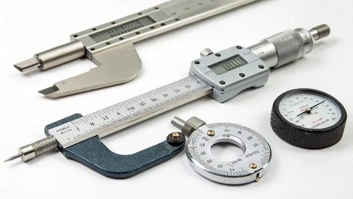
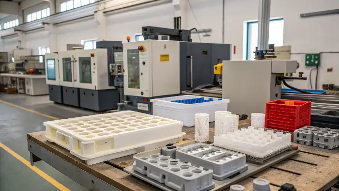
Getting the mold contact just right in injection molding is a real challenge. If there’s too little contact, you end up with defective parts. If there’s too much, you risk damaging your expensive mold or the parts themselves. This balancing act can lead to wasted material, frustrating production delays, and costly mold repairs if you don’t get it right. Understanding the optimal contact is crucial for producing high-quality parts and maintaining a smooth, efficient manufacturing process.
An injection molding product must contact the mold with enough force for good filling and cooling. But, too much force can damage the mold or the part. The mold needs to close with enough pressure to stop flash and fill completely. Yet, this pressure shouldn’t be too high for the machine or stress the mold. Finding that perfect closing force is key for quality parts without damage.

Getting this contact right is a big part of successful injection molding, something I learned early on in my career. But there’s more to it than just the closing force. As a designer like Jacky, you know that many factors contribute to a successful molding outcome. So, let’s explore some other important aspects that every designer and engineer should keep in mind to master the art of molding.
What are three key design considerations for injection mould design?
Designing an injection mold can feel overwhelming sometimes, with so many different factors to consider. I remember when I first started my own company, the learning curve was steep. If you overlook key design aspects, it can easily lead to poor part quality, frustrating manufacturing issues, and increased costs down the line. Focusing on a few critical design considerations from the very beginning can set you up for success and save a lot of headaches.
Three key design considerations for injection molds are: ensuring proper draft angles for easy part ejection, maintaining uniform wall thickness to prevent defects like sink marks and warping, and designing an effective gating and runner system for optimal material flow. These elements are fundamental to producing high-quality parts efficiently.

Let’s dive deeper into these critical areas. As someone who has seen countless designs, I can tell you that these three elements often make the difference between a smooth production run and a problematic one.
The Importance of Draft Angles
Draft angles are slight tapers added to the vertical walls of your part. Think of them like the gentle slope on the sides of an ice cube tray; they help the ice cubes pop out easily. Without draft angles, your plastic part can stick to the mold, leading to ejection problems, scuff marks, or even damage to the part or the mold. I’ve seen projects delayed simply because insufficient draft was applied.
The general rule is to apply at least 1 to 2 degrees of draft per side. For textured surfaces, you might need even more, sometimes up to 3 to 5 degrees, depending on the depth of the texture. It’s a small detail that has a huge impact on manufacturability.
Why Uniform Wall Thickness Matters
Imagine pouring water into a container with thick and thin sections. The thin sections will fill and cool differently than the thick ones. The same principle applies to molten plastic. Non-uniform wall thickness can cause a host of problems:
- Sink Marks: Thicker sections cool slower, and as they shrink, they can pull material from the surface, creating unsightly depressions.
- Warping: Differential cooling and shrinkage rates between thick and thin sections create internal stresses, causing the part to distort.
- Voids: Internal cavities can form in thick sections if the material solidifies on the outside before the inside has fully packed out.
Striving for uniform wall thickness throughout your part design is a golden rule. If thickness variations are unavoidable, make the transition gradual.
Designing Effective Gating and Runner Systems
The gate is the opening through which molten plastic enters the mold cavity, and the runner is the channel that delivers the plastic to the gate. The design of these elements is critical for several reasons:
- Filling Pattern: It determines how the cavity fills, which can affect part strength and appearance.
- Cycle Time: An efficient runner system minimizes material usage and can reduce cooling time.
- Gate Vestige: The gate leaves a small mark on the part, so its location needs careful consideration for aesthetic and functional reasons.
I always advise my clients to think carefully about gate type and location. For example, a submarine gate can be automatically trimmed, saving a secondary operation, but it might not be suitable for all materials or part geometries.
| Feature | Good Practice | Bad Practice | Impact of Bad Practice |
|---|---|---|---|
| Draft Angle | 1-2° minimum per side | 0° or insufficient angle | Sticking, scuffing, ejection issues |
| Wall Thickness | Uniform, gradual transitions if varied | Abrupt changes, overly thick sections | Sink marks, warping, voids, long cycles |
| Gate Location | Non-critical surface, balanced flow | Critical surface, unbalanced flow | Cosmetic defects, weld lines, warpage |
Paying attention to these three areas will significantly improve your mold designs and the quality of your final products.
What is the rule of thumb for injection molding?
Sometimes, in the complex world of injection molding, you just need some quick guidelines, not dense textbooks. I know when I’m discussing a new project with a client, they often appreciate some straightforward advice. Without some general rules, you might make common mistakes that slow down production or affect part quality. Knowing a few reliable rules of thumb can help you make faster, smarter decisions, especially in the early design stages.
A common rule of thumb in injection molding is to aim for uniform wall thickness throughout the part, typically between 1mm to 4mm for most common thermoplastics. Another is to incorporate draft angles of at least 1-2 degrees per side to facilitate part ejection. These guidelines help prevent defects and ensure manufacturability.

These rules of thumb are like the foundational knowledge I gained working on the factory floor. They are practical and have stood the test of time. Let’s explore these and a few others in more detail.
Wall Thickness: The Foundation of Good Parts
As mentioned before, uniform wall thickness is king. Most common thermoplastics work best with wall thicknesses between 1mm (0.040 inches) and 4mm (0.160 inches). Going thinner can lead to filling problems or weak parts. Going thicker can cause sink marks, voids, and excessively long cycle times due to increased cooling needs. If you absolutely must have varying thicknesses, try to make the transition as smooth and gradual as possible, typically no more than a 25-30% change.
Draft Angles: Helping Your Parts Come Out Smoothly
The 1-2 degree rule for draft angles is a good starting point. For every millimeter of depth, you should aim for about 0.017mm to 0.035mm of taper. This small angle makes a huge difference in how easily the part releases from the mold. Remember, textured surfaces need more draft. The deeper the texture, the more draft you’ll need. I’ve seen parts get stuck so badly that the ejector pins punched right through them, all because of insufficient draft.
Gate Placement and Cooling: More Than Afterthoughts
Another rule of thumb is to place gates in the thickest section of the part if possible. This allows the material to flow from thick to thin, helping to pack out the part effectively and reduce sinks. Also, try to keep gate locations away from aesthetically critical surfaces or areas that experience high stress.
For cooling, a general guideline is that cooling time often accounts for more than 50% of the total cycle time. Designing effective cooling channels in the mold is paramount. While this is more on the mold maker’s side, as a part designer, understanding this helps appreciate why certain design features might impact cycle time and cost.
Here’s a quick table summarizing some common rules:
| Aspect | Rule of Thumb Guideline | Why It’s Important |
|---|---|---|
| Wall Thickness | 1mm – 4mm, uniform | Prevents defects, ensures proper filling, controls cycle |
| Draft Angle | 1-2 degrees per side (more for textures) | Facilitates part ejection, prevents damage |
| Rib Height | Max 2.5x nominal wall thickness | Prevents sink marks opposite ribs |
| Rib Thickness | 50-60% of nominal wall thickness | Prevents sink marks, ensures proper filling of ribs |
| Corner Radii (Inside) | Min 0.5x nominal wall thickness | Reduces stress concentration, improves flow |
| Corner Radii (Outside) | Inside Radius + Wall Thickness | Maintains uniform wall thickness around corners |
These rules aren’t absolute laws, but they provide excellent starting points for robust part design in injection molding.
What is the standard tolerance for injection molding?
Designers, especially those like Jacky who work with precise components, often ask me how precise their plastic parts can actually be when made through injection molding. It’s a fair question because unrealistic tolerance expectations can lead to design revisions, increased costs, or parts that simply don’t fit or function as intended. Understanding standard tolerances helps set achievable goals for part accuracy from the outset.
Standard tolerance for injection molding typically ranges from ±0.005 inches (±0.127 mm) for general-purpose applications. Tighter tolerances are achievable, often down to ±0.002 inches (±0.05 mm) or even ±0.001 inches (±0.025 mm) for precision parts, but these usually increase tooling and production costs. Material choice and part design also heavily influence achievable tolerances.

Achieving tight tolerances is a common goal, but it’s a journey that involves careful planning and understanding the process capabilities. Let’s break this down further.
Understanding Dimensional Tolerances
Tolerance refers to the permissible limit or limits of variation in a physical dimension of a part. For injection molding, we’re usually talking about linear dimensions, diameters, and sometimes geometric tolerances like flatness or concentricity. When I started my CNC trading company, understanding tolerances became even more critical because machining and molding have different capabilities.
A "standard" or "commercial" tolerance is what can be reasonably expected from a well-maintained mold and a controlled process without extraordinary measures.
Factors That Influence Achievable Tolerances
Several factors come into play when determining how tight a tolerance can be held:
- Material Choice: Different plastics shrink at different rates and in different ways. Amorphous materials (like ABS, PC) generally have lower, more predictable shrinkage than semi-crystalline materials (like Nylon, PP, PE), making them better suited for tighter tolerances. Filled materials can also behave differently.
- Part Design: Complex geometries, non-uniform wall thicknesses, and the overall size of the part can make it harder to hold tight tolerances. Larger parts naturally have larger potential variations.
- Mold Quality: The precision of the mold itself is fundamental. A high-precision mold, often made from hardened steel, is necessary for tight tolerance parts. This, of course, means higher upfront tooling costs.
- Process Control: Consistent machine parameters (temperature, pressure, time) are vital. Even small variations can affect part dimensions.
Balancing Precision and Cost
It’s crucial to specify tolerances that are truly necessary for the part’s function. Over-tolerancing, or specifying tighter tolerances than required, significantly increases costs. This is because it might necessitate:
- More expensive mold materials and construction.
- More precise and potentially slower machining for the mold.
- More sophisticated process control and monitoring.
- Higher scrap rates if parts fall out of the tighter tolerance window.
Here’s a general idea of tolerance grades, though specific standards like ISO 20457 or DIN 16742 provide more detailed classifications:
| Tolerance Grade | Typical Range (for a 25mm/1 inch dimension) | Considerations |
|---|---|---|
| Commercial/Standard | ±0.1 mm to ±0.25 mm (±0.004" to ±0.010") | Good for general applications, most cost-effective |
| Fine/Precision | ±0.025 mm to ±0.1 mm (±0.001" to ±0.004") | Requires careful design, material selection, & process control |
| Very Fine/High Precision | < ±0.025 mm (< ±0.001") | Specialized applications, very high cost, challenging |
Always discuss your tolerance requirements with your molder early in the design process. This ensures that expectations are aligned and the most cost-effective approach is chosen.
What are the ISO standards for injection molding?
Navigating the world of international standards for injection molding can sometimes feel like wading through alphabet soup. But, as someone who has helped clients grow their businesses, often internationally, I can tell you that these standards are important. Without awareness of relevant ISO standards, you might face issues with quality consistency, material specifications, or even hurdles in international trade. Knowing key ISO standards provides a common language and a framework for quality and communication in our industry.
Several ISO standards apply to injection molding. Key ones include ISO 294 (Plastics — Injection moulding of test specimens of thermoplastic materials), ISO 20457 (Plastics — Moulds — General requirements), and standards for specific materials like ISO 178 for flexural properties. These standards help ensure consistency in testing, mold design, and material quality.

These standards aren’t just bureaucratic hurdles; they are tools that help us all achieve better results. Let’s look a bit closer at why they matter and which ones are particularly relevant.
Why ISO Standards Matter in Molding
ISO (International Organization for Standardization) develops and publishes international standards. In injection molding, these standards help to:
- Ensure Quality and Consistency: They provide guidelines for materials, testing procedures, and mold design, leading to more predictable outcomes.
- Facilitate Communication: Using standardized terminology and specifications makes it easier for designers, mold makers, and material suppliers to understand each other, regardless of where they are located.
- Promote Safety: Some standards address safety aspects of machinery and processes.
- Support International Trade: Compliance with ISO standards can be a requirement for accessing certain markets.
When I started CKMOLD, my goal was to make mold knowledge accessible, and understanding standards is a part of that professional knowledge.
Key ISO Standards for Your Reference
While there are many ISO standards related to plastics, here are a few that are particularly relevant to injection molding:
- ISO 294 Series (e.g., ISO 294-1, ISO 294-3): This series covers the injection molding of test specimens of thermoplastic materials. It specifies conditions for molding specimens used for determining material properties, ensuring that test results are comparable.
- ISO 20457:2018 (Plastics — Moulds — General requirements): This is a very important standard that replaced older ones like DIN 16749. It provides general requirements for the design, manufacture, and documentation of molds for plastics processing. It also includes information on tolerances for molded parts (replacing parts of DIN 16742).
- ISO 178 (Plastics — Determination of flexural properties): This standard specifies a method for determining the flexural strength and modulus of plastics, often using specimens molded according to ISO 294.
- ISO 527 Series (Plastics — Determination of tensile properties): Similar to ISO 178, but for tensile properties.
- ISO 10073 (Plastics — Moulds — Glossary of terms): Provides standardized terminology for molds, which is crucial for clear communication.
How Standards Benefit Your Projects
As a designer like Jacky, referencing these standards can be very beneficial. For example, when you specify a material, you can also refer to the ISO standard for its testing. When discussing mold requirements with a supplier, ISO 20457 can provide a common basis for expectations. If you’re designing parts that need specific dimensional accuracy, the tolerance tables within ISO 20457 (or previously DIN 16742) offer guidance.
Here’s a brief overview:
| ISO Standard Number | Brief Description | Relevance to Injection Molding |
|---|---|---|
| ISO 294 series | Molding of test specimens for thermoplastics | Ensures consistent material property testing |
| ISO 20457 | General requirements for molds, includes tolerances | Key standard for mold design, construction, and part tolerances |
| ISO 178 | Determination of flexural properties of plastics | Standard method for testing a key mechanical property |
| ISO 527 series | Determination of tensile properties of plastics | Standard method for testing another key mechanical property |
| ISO 10073 | Glossary of terms for molds | Promotes clear communication using standardized terminology |
While you don’t need to memorize all these standards, being aware of their existence and general scope can greatly enhance your professionalism and the success of your projects.
Conclusion
In injection molding, ensuring the product contacts the mold with just the right force is vital for quality. Beyond that, success hinges on smart design choices like draft angles and uniform walls, practical rules of thumb, understanding achievable tolerances, and leveraging ISO standards. Mastering these elements, as we’ve discussed, helps create better parts, smoother production, and ultimately, more successful projects in this fascinating field.
