Are you tired of designing a perfect plastic part on your screen, only to see it fail during production? Defects like sink marks, short shots, or warpage can cause massive headaches, leading to expensive tool modifications and frustrating project delays. What if you could foresee and fix these issues before a single piece of steel is ever cut? This is precisely where mold flow analysis becomes your most powerful ally in the design process.
Mold flow analysis is a computer simulation that predicts how melted plastic resin flows to fill an injection mold cavity. It’s a virtual prototype of the molding process. This powerful tool helps engineers and designers identify potential manufacturing defects, optimize the part and mold design, and fine-tune processing parameters like temperature and pressure. Ultimately, it helps ensure part quality, reduce development costs, and shorten the time to market by solving problems digitally, not physically.
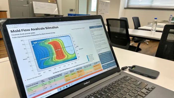
So, we know it’s a powerful simulation tool that acts like a crystal ball for plastic injection molding. It gives us incredible insight that was once only gained through expensive and time-consuming trial and error on the factory floor. But to truly appreciate its power, we need to understand what it’s analyzing and how it works.
Let’s dive deeper into the world of mold analysis to see how this technology can transform your design process from a game of chance into a precise science.
What exactly is mold analysis?
You’ve spent weeks perfecting a mold design in CAD, but a nagging uncertainty remains. Will it actually work as planned on the production floor? Will the cavity fill completely and evenly? Will the part cool without warping? Guessing is not a strategy. It leads to costly trial runs, wasted materials, and blown deadlines, putting both your budget and your reputation at risk. Mold analysis removes that guesswork, giving you the data-driven confidence that your design is robust and ready for manufacturing.
Mold analysis is the broad process of evaluating a mold design for manufacturability. This includes traditional checks for things like draft angles and wall thickness. Mold flow analysis is a specific, highly advanced type of mold analysis. It uses sophisticated software to simulate the entire injection process, providing deep insights into how the plastic will behave inside the mold. This allows you to predict and solve complex problems long before the mold is built.
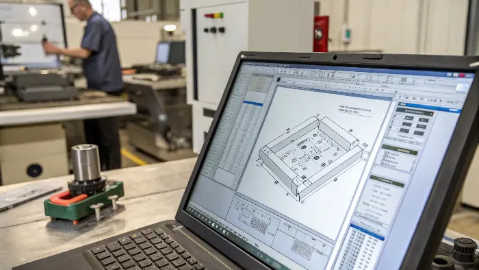
When we talk about mold analysis, we are really talking about two different levels of scrutiny. Both are essential, but they answer different questions and provide different levels of insight. Understanding both helps you appreciate just how revolutionary simulation-based analysis truly is.
Traditional Design for Manufacturability (DFM)
This is the foundational level of mold analysis. It involves a manual or semi-automated check of the part’s geometry against established best practices for injection molding. It’s about making sure the part can be easily ejected from the mold and will be structurally sound. I remember a project early in my career where we missed a tiny, 0.5-degree lack of draft on an internal rib. The part got stuck in the mold every single cycle, and we lost a week to rework the tool. A simple DFM check could have caught that.
Key DFM checks include:
| DFM Check | Why It’s Important |
|---|---|
| Draft Angles | Ensures the part can be ejected from the mold without drag marks or damage. |
| Wall Thickness | Uniform thickness prevents sink marks, voids, and warpage. |
| Corner Radii | Sharp internal corners create stress concentrations and can cause cracks. |
| Undercuts | Features that prevent direct ejection and require complex, costly mold actions. |
Simulation-Based Analysis
This is where mold flow analysis comes in. It goes far beyond the static geometry checks of DFM. It simulates the dynamic physics of the molding process: filling, packing, cooling, and warping. This digital approach provides a much deeper understanding. It’s like having X-ray vision into the mold as it operates. It helps us answer complex questions that traditional DFM can’t, like "Where will the weld lines form?" or "Will this thin section fill completely before the plastic freezes?" This is the level of analysis that separates good designs from great, highly optimized ones.
So, how does the plastic actually flow inside the mold?
Imagine injecting molten plastic into the complex cavity of your mold. It’s a black box. You can’t see how it fills, where it slows down, or where air gets trapped. This uncertainty is a huge risk, potentially leading to defects like short shots, burn marks, and weak points in the final part. You are essentially molding blind, just hoping for the best outcome. Understanding the flow process is critical, and mold flow analysis visualizes this entire journey, turning that black box into a clear, predictable process.
The flow of melted plastic inside a mold is a complex event governed by pressure, temperature, and the part’s geometry. The plastic is injected through a gate and travels along the path of least resistance, typically filling thicker sections before thinner ones. As it flows, it begins to cool and solidify against the mold walls. Mold flow analysis simulates this entire sequence, showing exactly how the cavity fills, second by second, and predicting how the material will behave.
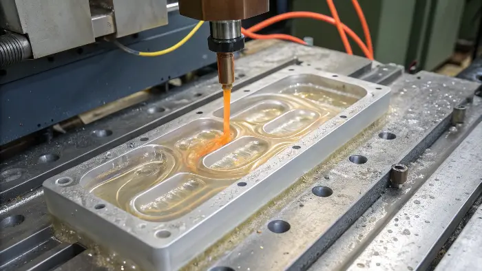
A mold flow simulation doesn’t just show a single snapshot in time. It breaks down the entire injection molding cycle into its critical phases, allowing us to analyze each one in detail. This is where the real problem-solving power lies.
The Filling Phase
This is the first and most fundamental part of the simulation. It shows the "flow front" of the plastic as it advances through the mold cavity. The analysis generates a color plot, often animated, showing which parts of the cavity fill first and which fill last. Here, we look for a "balanced" flow, where all flow paths fill at roughly the same time. We also look for "hesitation," where the flow front stalls in a thin area, and "race-tracking," where plastic rushes too quickly down a thick channel, creating an unbalanced fill and trapping air. The filling analysis is the primary tool for determining the best location and number of gates. I once saw a project for a large housing where the gate was poorly placed. One side of the part filled much faster than the other, causing extreme warpage. A simple filling analysis would have immediately shown the problem.
The Packing (or Holding) Phase
Once the mold is about 99% full, the process switches from the filling phase to the packing phase. The screw continues to push forward, applying a constant pressure to "pack" more material into the cavity. This is crucial for compensating for the material’s natural shrinkage as it cools and solidifies. An effective packing phase is what prevents ugly sink marks over ribs and bosses. The simulation shows how well the packing pressure is transmitted throughout the part, highlighting areas that might not get packed out properly and are at risk for sinks or internal voids.
The Cooling and Warpage Phase
This is often the most critical part of the analysis for parts with tight tolerances. As the plastic cools from its molten state, it shrinks. If one part of the component cools and shrinks much faster than another, massive internal stresses build up. When the part is ejected from the mold, these stresses are released, causing the part to warp and distort. The simulation analyzes the heat transfer from the plastic to the mold’s cooling channels and predicts the final warped shape of the part. This allows us to optimize the cooling layout to achieve uniform cooling, which is the key to a dimensionally stable part.
What key parameters does a mold flow analysis use?
You’re ready to run a simulation, but the software presents you with a long list of inputs and settings. What information is actually important to get a meaningful result? Using incorrect or generic data is a classic "garbage in, garbage out" scenario. An inaccurate simulation is arguably worse than no simulation at all, as it can give you a false sense of confidence and lead you to make poor design decisions. Understanding the core parameters is essential to ensure your analysis is accurate and reliable.
A successful mold flow analysis depends on three main categories of parameters. First is the specific material data for the chosen plastic resin, including its viscosity and thermal properties. Second is the part and mold geometry from your CAD files, which is converted into a calculation mesh. Third is the processing conditions, which are the settings for the injection molding machine, such as melt temperature, injection speed, and packing pressure. Getting these three inputs right is critical for an accurate simulation.
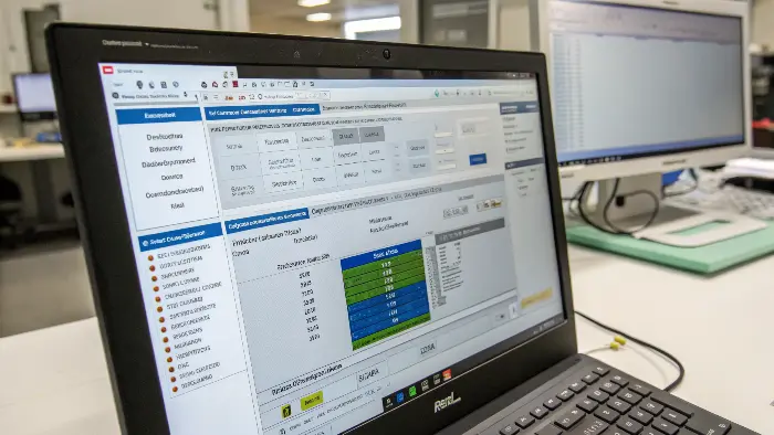
The accuracy of your simulation is directly tied to the quality of your inputs. Let’s break down these three critical areas.
Material Properties
This is the most important input. You can’t just select "ABS" from a generic list. You need the specific data for the exact grade of material you plan to use (e.g., "Sabic Cycolac MG38"). Reputable analysis software maintains vast libraries of material data, tested in a lab and provided by the material suppliers. I always tell my clients that the simulation is only as good as the material data you feed it. Key data points include:
- Viscosity Data: Describes how the material’s flow resistance changes with temperature and shear rate.
- PVT Data (Pressure-Volume-Temperature): Describes how the material’s density changes as it cools under pressure. This is critical for accurate shrinkage and warpage prediction.
- Thermal Properties: Includes specific heat and thermal conductivity, which govern how the material heats up and cools down.
Geometry and Mesh
The analysis software doesn’t work on your CAD model directly. It first converts the geometry of your part, runners, and cooling channels into a "mesh." This mesh is a network of thousands or millions of small elements (usually triangles or tetrahedrons). The software then performs its calculations on each of these tiny elements. The quality and density of the mesh are crucial. A finer mesh with more elements will capture small details and produce a more accurate result, but it will also take much longer to compute. It’s a trade-off between speed and accuracy.
Processing Conditions
These are the settings you would program into the actual injection molding machine. The goal of the analysis is often to find the optimal processing window.
| Parameter | What it Controls | Impact on Part Quality |
|---|---|---|
| Melt Temperature | The temperature of the plastic as it enters the mold. | Affects viscosity, flow length, and cooling time. |
| Mold Temperature | The temperature of the steel mold surfaces. | Influences surface finish, cooling rate, and warpage. |
| Injection Speed | The speed at which the cavity is filled. | Determines shear heating, weld line strength, and fill pattern. |
| Packing Pressure/Time | The pressure applied after filling is complete. | Compensates for shrinkage and prevents sink marks and voids. |
By running simulations with different processing conditions, you can determine the best settings to use in production before the first part is ever molded.
What are the Benefits of Performing a Mold Flow Analysis?
Carrying out a mold flow analysis has a variety of highly significant benefits that result in better product quality, efficient manufacturing, and reduced costs.
1. Optimization of Part and Mold Design
Mold flow analysis allows part geometry, gate location, wall thickness, and cooling channel location to be analyzed by engineers. If issues are found and corrected before mold cutting, the analysis can avoid costly design flaws and reduce the number of mold changes.
2. Improved Product Quality
The simulation also predicts common molding flaws such as air traps, weld lines, sink marks, short shots, and warpage. By eliminating these flaws at the design stage, manufacturers can produce parts with better dimensional accuracy, strength, and appearance.
3. Reduced Production Costs
By optimizing the mold design in the first place, mold flow analysis reduces trial-and-error during tool design and testing. It conserves material, reduces tooling rework expense, and reduces lead times, eventually saving cost and resources.
4. Enhanced Cycle Time Efficiency
Understanding the filling and cooling processes allows the manufacturers to maximize cycle times. Balanced filling and effective cooling can potentially lower molding cycle times dramatically, resulting in increased production throughput as well as energy conservation.
5. Enhanced Material Selection
Simulation of mold flow is able to forecast how different materials will flow within the mold. It helps in selecting the optimum resin based on flow behavior, mechanical properties, and shrinkage behavior to have the optimal match in performance and processing requirements.
6. Reduced Lead Time
The "lead time" is the time which elapses between the start of the injection molding process and the time when the finished product can be shipped to customers. Thus, the injection molders need to select a lead time reduction in order to fulfill the customers’ requirements and control the bulk market delivery of essential plastic assembly parts.
There are a number of factors which could affect lead time. The most prevalent type of defect is that of the injection molding process. However, Moldflow analysis shortens lead time by enabling early detection of possible defects prior to actual production.
7. Fewer Cases of Tooling Errors
Mold tooling is expensive, and mistakes can be economically catastrophic. Mold flow analysis helps to detect and prevent potential faults like unbalanced flow, high shear stress, or overpressure, reducing the likelihood of producing a faulty or inefficient tool.
8. Optimize Gate Position
Gate location is a factor in all injection moldings. Gates are entry points for plastic melt into a mold, which solidifies to form end products. Incorrect gate positions may cause non-filling of molten plastic in the mold regions. Incorrect gate position would result in the fabrication of faulty products due to uneven molten plastic flow. But moldflow analysis enables you to place gates in the optimal location through plastic flow analysis. So you can determine the right location for every gate in your mold and ensure that molten plastic flows into the mold evenly.
What software is actually used for mold flow analysis?
You’re convinced of the benefits of mold flow analysis, but a quick search reveals a market full of different software options. Which one is right for you? Choosing the wrong tool can be an expensive mistake. You could get locked into a platform that is too complex for your needs, not powerful enough for your complex parts, or doesn’t integrate well with your team’s existing CAD software. Knowing the key players and their strengths helps you make an informed decision that fits your specific requirements and budget.
The most widely recognized and established software for mold flow analysis is Autodesk Moldflow, which is often considered the industry gold standard. Other powerful and popular standalone options include Moldex3D and SIGMASOFT. Additionally, many major CAD platforms offer integrated simulation modules, such as SolidWorks Plastics and the Creo Mold Analysis Extension. The best choice depends on your team’s role, the complexity of your analysis, and your budget.
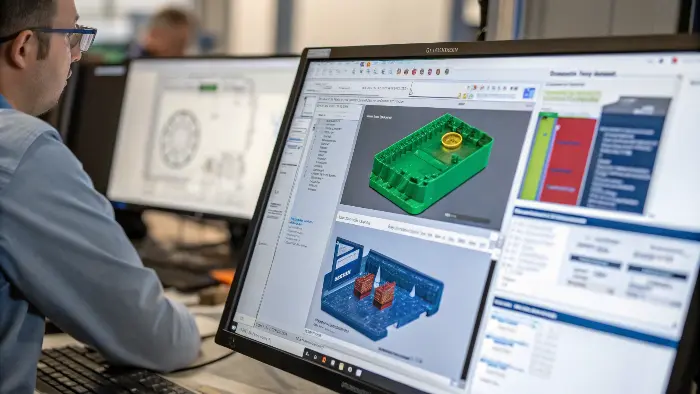
The software landscape can be broken down into two main categories: powerful, standalone analysis tools and convenient, integrated CAD solutions.
The Industry Standard: Autodesk Moldflow
Moldflow has been the leader in this space for decades. Its reputation is built on the accuracy of its solvers and, most importantly, its massive and meticulously curated material database. It comes in two main tiers:
- Moldflow Adviser: Aimed at part and mold designers like Jacky. It has a simplified interface and is designed for quick, upfront analysis to guide design decisions.
- Moldflow Insight: Aimed at dedicated CAE analysts. It offers the full suite of advanced tools for in-depth analysis of complex phenomena like core deflection, fiber orientation, and advanced cooling circuits.
I’ve used Moldflow for years on my most critical projects. Its depth and reliability are unmatched, especially when you need to solve a very difficult warpage or cooling problem.
Strong Competitors: Moldex3D and SIGMASOFT
- Moldex3D: A very strong competitor known for its excellent true 3D meshing technology. This can provide extremely high accuracy, especially for very thick, solid parts or parts with complex geometric details. It has great interoperability with other CAD and CAE platforms.
- SIGMASOFT: This software takes a unique approach by simulating the entire mold tool, not just the part cavity. It analyzes the thermal behavior of the complete mold over many production cycles. This is incredibly valuable for predicting how the mold will behave after it has reached a stable operating temperature, which is crucial for high-volume production.
Integrated CAD Solutions
These are analysis tools that live directly inside your primary CAD software, like SolidWorks Plastics or the tools available in Creo and Siemens NX.
| Software Type | Best For | Key Feature |
|---|---|---|
| Standalone (e.g., Moldflow) | Dedicated analysts, complex problems, high-stakes projects. | Highest accuracy, most extensive features, best material data. |
| Integrated (e.g., SW Plastics) | Part designers, early-stage DFM, quick checks. | Convenience, ease of use, seamless workflow within CAD. |
The main advantage of integrated solutions is convenience. A designer can run a quick fill analysis without ever leaving their familiar CAD environment. They are perfect for "first-look" DFM to catch major issues early. However, they generally lack the advanced capabilities and solver depth of the standalone packages. For a simple part, an integrated tool is often enough. For a complex, high-tolerance part, you’ll likely need the power of a dedicated tool.
How do you actually read a mold flow analysis report?
You’ve just received a 50-page analysis report from your simulation expert. It’s filled with brightly colored plots, complex graphs, and technical jargon. It’s completely overwhelming. If you can’t understand the results, you can’t take action. The entire analysis becomes a wasted effort, and the critical insights that could save your project from costly rework are lost in the noise. The key is knowing what to look for and how to interpret the story the analysis is telling you.
To effectively read a mold flow report, focus on a few key result plots. Start with the "Fill Time" plot to see the fill pattern and identify issues. Next, check the "Air Traps" and "Weld Lines" plots to find potential cosmetic or structural weak points. Then, look at the "Pressure at End of Fill" to ensure the machine can fill the part. Finally, review the "Volumetric Shrinkage" and "Warpage" plots to predict the final part’s quality and dimensional stability.

A comprehensive report can contain dozens of plots, but you can get 90% of the value by focusing on a handful of critical results that tell the story of your part’s journey from molten plastic to a solid component.
Filling Phase Results
These plots tell you if you can even make the part in the first place.
- Fill Time: This is a color plot or animation showing the flow front progression. You are looking for a smooth, balanced fill. Large color bands close together mean the flow is stalling, while areas that fill instantly indicate race-tracking.
- Weld Lines: These form where two or more plastic flow fronts meet. The report shows their exact location. You want to ensure they are not in areas that require high strength or have a critical cosmetic finish.
- Air Traps: This plot shows where pockets of air will be trapped by the converging flow fronts. Trapped air can cause burn marks on the part or prevent it from filling completely. This plot tells you exactly where vents need to be added to the mold tool.
Packing and Cooling Results
These plots tell you about the quality and efficiency of the process.
- Volumetric Shrinkage: This shows the percentage of shrinkage across the part. High variation in shrinkage is the enemy. Large differences in shrinkage from one area to another are a primary cause of sink marks and internal voids. The goal is to achieve a uniform shrinkage value.
- Time to Reach Ejection Temperature: This plot is a direct indicator of your cycle time. It shows which areas of the part take the longest to cool down to a safe ejection temperature. These "hot spots" dictate your overall cycle time and are prime targets for improved mold cooling.
The Final Verdict: Warpage Analysis
This is often the most important result for functional parts. It simulates how the part will deform and distort due to uneven shrinkage and cooling stresses after it is ejected from the mold. The report will show a color plot of the displacement and can even animate the deformation, exaggerating it so you can clearly see how it will bend or twist. I always tell my team: don’t just look at the pretty pictures. Look at the numbers. The analysis will give you specific displacement values (e.g., "0.5mm of warpage in the Z-direction"). You must compare this predicted value to your part’s dimensional tolerance on the drawing to decide if the design is acceptable or if changes are needed.
Is Mold Flow Analysis Necessary for All Applications?
Mold flow analysis is a useful tool when injection molding, but its use in all cases will be based on a wide range of factors such as part complexity, volume of production, material selection, and quality demands. It’s not strictly necessary in all cases, but it can assist significantly in most cases.
When Mold Flow Analysis Is Needed
1. Intricate Part Geometry
Parts with intricate geometries, thin section thickness, non-uniform wall thickness, or undercuts have the potential to create non-uniform flow, generation of air, or warpage. Mold flow analysis is highly recommended in these cases to foresee and rectify issues beforehand.
2. High-Volume Production
In production in large volumes, one defective item can lead to enormous losses. Mold flow analysis ensures first-time-right tooling, which eliminates the possibility of defective batches and costly rework.
3. Critical Applications and Tight Tolerances
When the product has to comply with rigorous dimensional or mechanical requirements—e.g., in the automotive, medical, or aerospace industries—accuracy is not a choice. Mold flow computer analysis aids in parts verification to specs.
4. Multi-Cavity or Family Molds
It is possible to have non-uniform pressure distribution or unequal filling in multi-cavity molds. Mold flow analysis balances runner systems and brings all cavities to parity.
5. Application of Unusual or Special Materials
Simulation is employed to predict how the material would behave with new or difficult-to-form resins so that better material selection and process optimisation can be achieved.
When Mold Flow Analysis May Not Be Required
1. Simple Designs
For low-complexity part shapes, uniform wall thickness, and minimal functional or aesthetic demands on the part, experienced mold designers can typically follow standard practice design without the necessity of a simulation.
2. Low-Volume Runs or Prototype
If you’re making a low-volume batch or just experimenting with early-stage prototypes, the time and expense of mold flow analysis may be more than it’s worth—especially if the risk of defect is low.
3. Repeat Designs
If the mold is a duplicate of an existing design that has already been tested (same material, same size), analysis is not required unless changes are planned.
Conclusion
Mold flow analysis is not just a fancy software tool; it’s a fundamental shift in how we approach plastic part design. It moves us from a world of guesswork and expensive physical prototypes to one of data-driven decisions and digital optimization. By simulating the filling, packing, and cooling phases, it allows us to solve problems before they exist. It’s an essential investment that prevents costly mold rework, reduces development time, and ultimately leads to higher-quality products.
