
Injection mold design begins by translating product function, material, geometry, appearance, volume and acceptance requirements into a repeatable tool and process. Early DFM can prevent avoidable steel changes, but production readiness still requires trials and evidence.
Injection mold design basics are the decisions that let a product become a repeatable molded part. Product designers do not need to design every steel component, but they should understand how draft, wall thickness, parting line, gate, cooling, venting, ejection, surface and tolerances affect cost and production risk. Early collaboration prevents many avoidable tool changes.
Related CKMOLD resources: mold design services, DFM analysis, prototype injection molding.
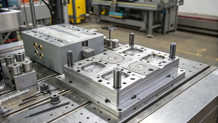
Injection mold design is the process of creating a specialized tool, the mold, that shapes molten plastic into a finished part. At its core, a mold consists of two halves: a cavity side (A-side) and a core side (B-side). When closed, they form a hollow space matching the part’s geometry. Hot, liquid plastic is then forced into this cavity under immense pressure. The design must meticulously account for how the plastic flows, cools, and shrinks, and how the final part will be safely ejected.

Start With the Product Definition, Not a Generic Mold Layout
Mold design starts with the released product definition: CAD/drawing revision, exact resin and color, annual/lifetime volume, machine/destination, CTQs, visible surfaces, assembly, use environment and acceptance plan. Those inputs drive draw direction, parting, shrinkage, cavities, feed, cooling, venting, actions, ejection, steel and correction strategy. The product-to-mold interface guide covers that handoff, while the precision-molding guide explains how to define critical requirements and measurement evidence.
Radii, draft, ribs and walls should be justified for the selected grade and geometry. Fixed numbers such as 1–2° draft, one rib ratio or one shrinkage allowance are screening clues only; supplier design data and analysis must be applied to the actual feature.

Radii – Why They are Necessary
While not necessarily required, radii (angled internal and external corners) are strongly advisable in injection molding for a number of practical reasons.
Internal radii can reduce stress concentration and abrupt flow/steel transitions, but the suitable radius depends on function, wall, exact grade, load and tool construction. A radius does not by itself guarantee complete fill or structural integrity; record the design basis and validate critical regions.
Secondly, radiusing will strengthen and harden the part. Sharp internal edges will function as a stress concentrator, which under tension has a tendency to crack. A simple radius will distribute the stress evenly and strengthen the part over time.
Last, ejection of the part is easier with radiused corners. Rounded edges will not catch on the mold when ejecting as readily, leaving less opportunity for warping or breaking the part. This allows for a faster, smoother production cycle.
The Injection Molding Cycle: A Step-by-Step Breakdown
The process is a finely tuned dance of pressure, temperature, and time.
| Stage | Description | the engineering guidance |
|---|---|---|
| 1. Clamping | The two halves of the mold (core and cavity) are pressed together by a powerful hydraulic or electric clamping unit. | The force here is immense, often hundreds or thousands of tons. It has to be strong enough to hold the mold shut against the intense pressure of the injected plastic. If the clamp fails, you get “flash,” where plastic seeps out of the parting line, creating a mess and a defective part. |
| 2. Injection | Plastic pellets are fed from a hopper into a heated barrel, where a reciprocating screw melts and mixes them. The screw then pushes forward, injecting the molten plastic into the mold cavity. | Injection velocity, pressure limit and transfer must be developed for the exact part, grade, gate and machine. Verify a stable process window rather than applying a ‘slow/fast’ recipe. |
| 3. Dwelling & Cooling | After the cavity is filled, pressure is maintained for a short period (dwelling) to pack out the part and compensate for shrinkage. Then, the part is left to cool and solidify. | Cooling is often the longest part of the cycle, accounting for up to 80% of the total time. An efficient cooling channel design inside the mold is crucial for reducing cycle time and preventing defects like warping. This is where good mold design really pays off. |
| 4. Ejection | The clamping unit opens the mold. An ejection system, usually consisting of pins or plates, pushes the solidified part out of the core side of the mold. | For the part to come out cleanly, the design must include draft angles (slight tapers on the walls). |
Understanding this cycle is the foundation. Every decision in mold design is made to make this process as smooth, fast, and reliable as possible.
What is injection mold design?
You understand the molding process, but what exactly goes into designing the tool that makes it all happen? It’s a common blind spot. Without this knowledge, your product designs might be physically impossible or incredibly expensive to manufacture. This can lead to major project setbacks, budget revisions, and a lot of wasted time. Understanding injection mold design is about translating a 3D product model into a functional, durable, and efficient manufacturing tool.
Injection mold design engineers the cavity/core and the feed, venting, cooling, support, actions and ejection needed for the defined part. A released design should state its assumptions and be verified by trial evidence for quality, cycle and serviceability rather than promising maximum life or minimum time.

Choose Cavity Architecture From Demand and Control Risk
A single-cavity tool can simplify balance and correction but may not meet output. An identical multi-cavity tool can reduce machine cost per part but increases mold size, feed/cooling balance, maintenance and cavity-level inspection. A family mold combines different parts and therefore adds fill/pack/cooling balance and demand-ratio risk.
Compare accepted output, not nominal cavities: accepted parts per hour = cavities × 3600 ÷ cycle seconds × uptime × yield. Treat uptime and yield as assumptions until trial or production evidence exists. Review the multi-cavity mold decision scope before approving cavity count.
Request cavity identification, runner/hot-runner balance evidence, separate cavity measurements, shutoff/maintenance access and a plan for disabling or repairing one cavity without losing traceability.
Release the Mold Through Measurable Decisions
- Approve DFM: draw, parting, shutoffs, undercuts, wall transitions and visible witness.
- Approve architecture: cavities, feed, cooling, venting, support, actions and ejection.
- Approve interfaces: press, hot runner, electrical, water, hydraulic/pneumatic, robot and safety.
- Approve acceptance: resin/machine, T1 objectives, sample identification, CTQs, appearance, function and correction responsibility.
- Approve handover: as-built design, bill of materials, steel/heat-treatment records, process sheet, spares and maintenance.
The public scope of ISO 20457:2026 explains that plastic-part dimensional control depends on material, part design, tool layout and process. Use its current scope only where contractually applicable; it is not a universal tolerance table copied into every drawing.

Draft and Parting Line Define Release
Draft allows the part to leave the core or cavity without scuffing or excessive force. The parting line should separate the mold cleanly while protecting appearance, sealing and functional surfaces. Undercuts may require slides, lifters or a redesign.
Wall Thickness and Geometry Control Flow
Consistent wall transitions, radii, ribs and bosses help reduce sink, short shots, stress and warpage. A functionally necessary thick section should be cored or transitioned deliberately, not ignored because the part looks acceptable in CAD.
Gates, Runners and Vents Manage the Melt
The gate controls where and how resin enters, the runner distributes it and vents allow air to escape. These decisions affect weld lines, packing, appearance, fiber orientation, pressure and cavity balance.
Cooling and Ejection Protect the Part
Cooling controls cycle and shrinkage; ejectors, sleeves, lifters and slides release the part. Product features should give the mold enough access to cool and eject without marks or distortion.
Make Tolerances and Surfaces Measurable
Critical dimensions should connect to datums and inspection methods. Texture, gloss, polish, gate marks, ejector marks and parting lines should be defined by a real acceptance standard. This information gives the moldmaker a clear target.
Injection Mold Design Basics: Buyer Review Checklist
- Review draft, parting line, undercuts, wall, ribs, bosses and radii in early DFM.
- Choose gate, runner, venting and cavity balance from flow and appearance requirements.
- Provide cooling access and ejection direction for the actual geometry.
- Tie critical tolerances and surface requirements to datums and inspection methods.
- Use a documented product-to-mold handoff before the tool structure is finalized.
FAQ
What should product designers consider first for injection molding?
Start with function, material, volume, wall thickness, draft, parting line, undercuts, surface and critical assembly interfaces.
Why is the parting line important?
It affects appearance, flash, tooling complexity, ejection, sealing and where the mold can split around the product.
Conclusion
In the end, mastering injection mold design comes down to a few key areas. It starts with a solid grasp of the molding process itself, followed by knowing the core components of the mold. Most importantly, it’s about applying the fundamental design principles like draft, uniform walls, and shrinkage. Focusing on these details is how you create efficient, reliable molds that turn great ideas into high-quality, manufacturable products. This foundation is your key to success.