

Are you tired of designing a suitable plastic part on your screen, only to see it fail during production? Defects like sink marks, short shots, or warpage can cause massive headaches, leading to expensive tool modifications and frustrating project delays. What if you could foresee and fix these issues before a single piece of steel is ever cut? This is precisely where mold flow analysis becomes your most powerful ally in the design process.
Mold flow analysis is a simulation-based engineering method for studying how polymer fills, packs and cools inside a proposed mold. It can expose gate, pressure, weld-line, air-trap, balance, cooling and warpage risks before steel is cut. The project value comes from avoiding late changes and making trade-offs visible, not from treating a simulation as a support.
Related CKMOLD resources: DFM analysis, mold design, mold testing and validation.
Mold-flow analysis is a simulation used to compare defined material, geometry, feed and process assumptions. It can identify risks and guide design or trial plans, but it does not guarantee quality, cost or launch timing; confidence depends on inputs, analyst decisions and physical correlation.
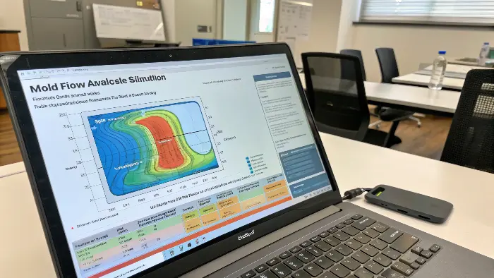
So, we know it’s a powerful simulation tool that acts like a crystal ball for plastic injection molding. It gives us incredible insight that was once only gained through expensive and time-consuming trial and error on the factory floor. But to truly appreciate its power, we need to understand what it’s analyzing and how it works.
What Mold-Flow Analysis Is—and Is Not
A mold-flow study is a decision model for a defined CAD revision, runner/hot-runner, resin grade, machine and process assumption. It can compare fill sequence, pressure, temperature, shear, weld/air locations, packing, cooling and warpage outputs supported by the selected module. It does not certify that a part will pass or that no steel correction will be needed.
The useful deliverable is not a set of color plots. It is a record of inputs, assumptions, alternatives, result sensitivity, engineering decision and validation plan. Keep conventional DFM and simulation connected: geometry or acceptance issues visible in the drawing do not need a solver to be real. The CAD-versus-FEA guide clarifies the boundary between released geometry and a physics model.
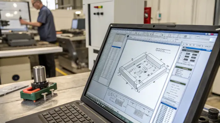
So, how does the plastic actually flow inside the mold?
Imagine injecting molten plastic into the complex cavity of your mold. It’s a black box. You can’t see how it fills, where it slows down, or where air gets trapped. This uncertainty is a huge risk, potentially leading to defects like short shots, burn marks, and weak points in the final part. You are essentially molding blind, just hoping for the best outcome. Understanding the flow process is critical, and mold flow analysis visualizes this entire journey, turning that black box into a clear, predictable process.
The flow of melted plastic inside a mold is a complex event governed by pressure, temperature, and the part’s geometry. The plastic is injected through a gate and travels along the path of least resistance, typically filling thicker sections before thinner ones. As it flows, it begins to cool and solidify against the mold walls. Mold flow analysis simulates this entire sequence, showing exactly how the cavity fills, second by second, and predicting how the material will behave.
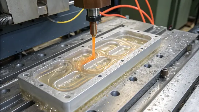
A mold flow simulation doesn’t just show a single snapshot in time. It breaks down the entire injection molding cycle into its critical phases, allowing us to analyze each one in detail. This is where the real problem-solving power lies.
The Filling Phase
During velocity-controlled filling, the advancing melt front displaces air and loses pressure and temperature through the feed system and cavity. Review fill pattern, pressure use, flow-front temperature, shear and air/weld locations together. A plot is meaningful only when gate/runner geometry, machine limits, vent assumptions and material data match the proposed process.
The Packing (or Holding) Phase
Once the mold is about 99% full, the process switches from the filling phase to the packing phase. The screw continues to push forward, applying a constant pressure to “pack” more material into the cavity. This is crucial for compensating for the material’s natural shrinkage as it cools and solidifies. An effective packing phase is what prevents ugly sink marks over ribs and bosses. The simulation shows how well the packing pressure is transmitted throughout the part, highlighting areas that might not get packed out properly and are at risk for sinks or internal voids.
The Cooling and Warpage Phase
This is often the most critical part of the analysis for parts with tight tolerances. As the plastic cools from its molten state, it shrinks. If one part of the component cools and shrinks much faster than another, massive internal stresses build up. When the part is ejected from the mold, these stresses are released, causing the part to warp and distort. The simulation analyzes the heat transfer from the plastic to the mold’s cooling channels and predicts the final warped shape of the part. This allows us to optimize the cooling layout to achieve uniform cooling, which is the key to a dimensionally stable part.
Inputs Determine the Confidence of the Result
Use the exact geometry and thickness, mesh appropriate to the solver, complete feed system, cavity count, inserts, mold/coolant description, material grade and required process/machine limits. Autodesk states that different grades of one material can have different properties and that choosing the wrong grade affects result quality; its material-database guidance also provides testing routes for unlisted grades.
Check viscosity, thermal and pvT data for fill/pack; shrinkage and mechanical/orientation data for warpage; and the database’s quality indicators. Autodesk’s Material Quality Indicators distinguish tested from supplemental or incomplete data. A generic family substitute should be shown as a limitation and sensitivity case, not hidden.
What are the Benefits of Performing a Mold Flow Analysis?
Carrying out a mold flow analysis has a variety of highly significant benefits that result in better product quality, efficient manufacturing, and reduced costs.
1. Optimization of Part and Mold Design
Mold flow analysis allows part geometry, gate location, wall thickness, and cooling channel location to be analyzed by engineers. If issues are found and corrected before mold cutting, the analysis can avoid costly design flaws and reduce the number of mold changes.
2. Improved Product Quality
The simulation also predicts common molding flaws such as air traps, weld lines, sink marks, short shots, and warpage. By eliminating these flaws at the design stage, manufacturers can produce parts with better dimensional accuracy, strength, and appearance.
3. Reduced Production Costs
By optimizing the mold design in the first place, mold flow analysis reduces trial-and-error during tool design and testing. It conserves material, reduces tooling rework expense, and reduces lead times, eventually saving cost and resources.
4. Enhanced Cycle Time Efficiency
Understanding the filling and cooling processes allows the manufacturers to maximize cycle times. Balanced filling and effective cooling can potentially lower molding cycle times dramatically, resulting in increased production throughput as well as energy conservation.
5. Enhanced Material Selection
Simulation of mold flow is able to forecast how different materials will flow within the mold. It helps in selecting the optimum resin based on flow behavior, mechanical properties, and shrinkage behavior to have the optimal match in performance and processing requirements.
6. Reduced Lead Time
The “lead time” is the time which elapses between the start of the injection molding process and the time when the finished product can be shipped to customers. Thus, the injection molders need to select a lead time reduction in order to fulfill the customers’ requirements and control the bulk market delivery of essential plastic assembly parts.
There are a number of factors which could affect lead time. The most prevalent type of defect is that of the injection molding process. However, Moldflow analysis shortens lead time by enabling early detection of possible defects prior to actual production.
7. Fewer Cases of Tooling Errors
Mold tooling is expensive, and mistakes can be economically catastrophic. Mold flow analysis helps to detect and prevent potential faults like unbalanced flow, high shear stress, or overpressure, reducing the likelihood of producing a faulty or inefficient tool.
8. Optimize Gate Position
Gate alternatives can be compared for fill pattern, pressure, temperature, shear, air/weld location, packing and visible vestige. The model can narrow the choice, but ‘optimal’ requires product, tool, machine and acceptance tradeoffs plus trial correlation.
Choose the Software Module From the Engineering Question
Autodesk Moldflow, Moldex3D, SIGMASOFT and CAD-integrated tools differ by solver, process modules, meshing, material data, automation and reporting. No product is universally the “gold standard” for every decision, and a brand name does not prove analyst competence.
Ask the supplier to identify software/version, analysis sequence, mesh type/quality, material record, machine/process limits, runner/hot-runner detail and result quantities. For specialized processes, verify that the licensed module and material model actually support them.
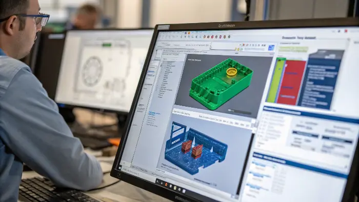
Read the Report as a Chain of Decisions
- Confirm model revision, units, cavities, feed system and material grade.
- Check mesh diagnostics and input quality before reading results.
- Read fill, pressure, temperature, shear, air/weld and clamp together.
- Read packing/cooling/shrinkage before accepting sink or warpage conclusions.
- Compare alternatives on the same assumptions and identify sensitivity.
- Convert the result into gate, wall, vent, cooling, process and trial actions.
At T1, compare controlled short shots, pressure/position traces, part weight, temperature and cavity-level dimensions with the model. Correlation—not software prestige—raises confidence for the next decision.
Is Mold Flow Analysis Necessary for All Applications?
Mold flow analysis is a useful tool when injection molding, but its use in all cases will be based on a wide range of factors such as part complexity, volume of production, material selection, and quality demands. It’s not strictly necessary in all cases, but it can assist significantly in most cases.
When Mold Flow Analysis Is Needed
1. Intricate Part Geometry
Parts with intricate geometries, thin section thickness, non-uniform wall thickness, or undercuts have the potential to create non-uniform flow, generation of air, or warpage. Mold flow analysis is highly recommended in these cases to foresee and rectify issues beforehand.
2. High-Volume Production
For high-volume programs, simulation may reduce avoidable iterations by comparing risks before steel. It cannot eliminate defective batches or rework; validate the selected design with controlled trials, process-window evidence and cavity-level acceptance.
3. Critical Applications and Tight Tolerances
When the product has to comply with rigorous dimensional or mechanical requirements—e.g., in the automotive, medical, or aerospace industries—accuracy is not a choice. Mold flow computer analysis aids in parts verification to specs.
4. Multi-Cavity or Family Molds
It is possible to have non-uniform pressure distribution or unequal filling in multi-cavity molds. Mold flow analysis balances runner systems and brings all cavities to parity.
5. Application of Unusual or Special Materials
Simulation is employed to predict how the material would behave with new or difficult-to-form resins so that better material selection and process optimisation can be achieved.
When Mold Flow Analysis May Not Be Required
1. Simple Designs
For low-complexity part shapes, uniform wall thickness, and minimal functional or aesthetic demands on the part, experienced mold designers can typically follow standard practice design without the necessity of a simulation.
2. Low-Volume Runs or Prototype
If you’re making a low-volume batch or just experimenting with early-stage prototypes, the time and expense of mold flow analysis may be more than it’s worth—especially if the risk of defect is low.
3. Repeat Designs
If the mold is a duplicate of an existing design that has already been tested (same material, same size), analysis is not required unless changes are planned.
What the Analysis Can Answer
It can compare gate location, runner balance, fill time, pressure, weld lines, air traps, cavity weights, packing, cooling and predicted deformation. It can also show whether a machine has realistic pressure or injection-rate reserve for the proposed geometry.
How It Saves Cost and Schedule
Moving a gate or adding a cooling circuit is easier before machining than after a mold trial. Analysis can help avoid an oversized machine, poor cavity balance, visible weld line, thin-wall short shot or correction cycle. The saving should be evaluated against the cost of the study and the risk of uncertain inputs.
Use Product Requirements to Interpret Results
A predicted weld line matters if it crosses a load path or visible zone. A pressure increase matters if the machine lacks reserve. A warpage contour matters if it affects a datum or assembly. Engineers should convert plots into decisions and document the trade-off.
Inputs and Limitations Define Confidence
Geometry, mesh, resin grade, viscosity, shrinkage, gates, cooling, mold temperature and machine assumptions drive the result. Generic data, missing steel deflection, uncertain boundary conditions and material variation limit confidence. A report should state what it knows and what it does not.
Correlate the Model With Trial Evidence
Use short shots, cavity weights, pressure, temperatures, dimensions and defect locations to compare prediction and reality. Correlation improves future designs and prevents overconfidence in a model that does not represent the real tool.
Mold Flow Analysis and How Can It Save a Project: Buyer Review Checklist
- Define the project decision: gate, cavity, pressure, cooling, material or warpage risk.
- Use realistic geometry, material, machine, gate, cooling and process assumptions.
- Interpret results against functional, appearance, quality and schedule requirements.
- Record risks, actions, owners and limitations in the engineering report.
- Correlate results with trial evidence and update assumptions when needed.
FAQ
Is mold flow analysis required for every mold?
No. It is most useful for thin walls, complex flow, multi-cavity, filled materials, visible weld-line risk or expensive corrections.
Can mold flow analysis support a good part?
No. It predicts behavior under assumptions; actual molds, material lots, machines and trials still determine production capability.
Conclusion
Mold flow analysis is not just a fancy software tool; it’s a fundamental shift in how we approach plastic part design. It moves us from a world of guesswork and expensive physical prototypes to one of data-driven decisions and digital optimization. By simulating the filling, packing, and cooling phases, it allows us to solve problems before they exist. It’s an essential investment that prevents costly mold rework, reduces development time, and ultimately leads to higher-quality products.