
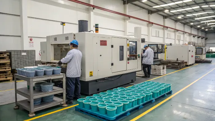
The mold presents a finished piece of plastic that has defects, which cost you both in time and savings. You end up with reject pile and you are unsure of whether it is the material, the machine itself or the mold that is the problem. Every non-functional component is a waste of money and time. An effective systematic evaluation process should enable you to identify the core of the problem and then you will be able to put your production back on SS.
Evaluating an injection molding problem starts with deciding whether the issue is a defect, a measurement variation, a process drift or a product requirement conflict. Short shots, flash, sink, burn, flow marks, warpage and dimensional changes should be categorized by location, timing, cavity and condition before the team changes settings. Triage makes the investigation faster and less disruptive.
Related CKMOLD resources: mold testing and validation, production injection molding, mold repair or modification.
To identify injection molding defects, start with the type of defect, e.g., flash, sink marks, or short shots. Then, step by step, examine the four main areas: the plastic material, the injection mold, the molding machine, and the process parameters. This “4M” approach (Material, Mold, Machine, Method) allows you to regulate variables and try changes in a logical manner. Documenting each change and result is necessary to reach a repeatable solution and avert repeat defects.

It can be like playing a detective to identify precisely the cause of a molding problem. It needs an acute observation and a clear strategy. However, before one can find a solution to a problem, one has to understand what he/she is seeking. Let us see what the typical perpetrators you will find back on the factory floor. Learning such defects will get you started in understanding the molding process and how you can make all the parts meet your standards.
Classify the Symptom Before Adjusting the Process
This page is a triage guide: identify, contain and route the problem before a deeper root-cause study. Describe what is observed—not what is assumed. A short shot is missing material; sink is a surface depression over local shrinkage; warpage is shape deviation; splay is a surface streak; a burn can arise from trapped gas or degradation. Similar-looking marks can have different causes. For the first symptom, follow the dedicated short-shot corrective sequence.
Record part/cavity, location, first occurrence, frequency, material/lot, machine/mold, shift, cycle position and the measurement or photo. Quarantine the affected window and compare known-good parts before changing settings.

Read Inputs Together With Process Outputs
Setpoints alone do not explain a defect. Compare actual fill time, peak pressure, velocity/pressure transfer, cushion, recovery, screw position, cycle segments, mold/coolant temperature, part weight and cavity identity. A pressure change can mask a blocked vent or worn parting line; a temperature change can create degradation or cycle drift.
Use the exact material grade’s processing range and the machine’s pressure conversion. Change one controlled factor only when the output data and defect mechanism justify it, and define a stop condition before the test.

What are the fundamental constraints of injection molding?
Your CAD design of the product is awesome, yet the manufacturer claims it is unlikely to mold its way. This is because, it will subject you to timewasting and frustrating redesigns and this may lead to a delayed project launch as well as the distortion of your original design concept. You feel constrained with the process. By being aware of the limitations of injection molding right at the beginning, you will be able to create parts which are not just functional, but also manufacturable.
Injection-molding constraints arise from product function and geometry, exact material, mold architecture, machine/process capability, measurement and the commercial plan. Draft, wall transitions and undercuts are common DFM issues, but temperature, shrinkage and tooling investment are not the only material or project constraints.

For early DFM, trace how melt fills, how the part cools and shrinks, and how it releases. This does not replace analysis or trials, but it exposes missing draft, abrupt sections, trapped steel, gate/vent risks and unsupported acceptance assumptions before tooling.
Design, Material, and Tooling Constraints
These three areas are where the rules of the road are written for injection molding. Ignoring them leads to trouble.
Design Constraints (DFM)
Product DFM is one controllable input: define functional surfaces, datums, loads, appearance, material and release needs so the mold and process can be evaluated against them.
- Thickness of the wall: This is the golden rule. Walls should be as uniform in thickness as possible. Thick parts cool more slowly than thin parts, leading to differential shrinkage, which leads to warping and sink marks.
- Draft Angles: All components need a minor taper on their vertical edges, referred to as a draft angle. 1-2 degrees will normally be enough. This allows the part to be easily pushed out of the mold. Without it, you will get drag marks or the part will stick.
- Radii and Corners: Thin interior corners create stress concentrations in the part and are difficult to fill. Putting a small radius (fillet) on all of the corners makes the part stronger and enables the plastic to flow more easily.
- Undercuts: Undercuts are side holes or clips that stop the part from being pushed straight out of the mold. They may be made but are hard and expensive to achieve with intricate mold mechanisms like side-actions or lifters.
Material and Tooling Constraints
The limitation also lies in the material you use, as well as on whatever tool you make. The reaction of different plastics to shrinking is different. To cite an example, Polypropylene (PP) can shrink twice as much than Acrylonitrile Butadiene Styrene (ABS). This contraction has to be considered in designing the mold. A big limitation is the mold itself. A non-complex, just open and shut mold is fairly inexpensive and quickly produced. A complex mold- multiple side-actions to form undercuts will cost far much more and will also take very long time to build. It is a trade off between the cost of tooling and the complexity of the parts and there is generally an element of trade off in any project.
Use Technology to Preserve Evidence, Not to Guess
Machine traces, cavity-pressure or temperature sensors, vision, part-weight trends and simulation can narrow a hypothesis when they are calibrated and connected to cavity-level results. Automation does not diagnose by itself. Define the signal, sample rate, alarm limit, reaction plan and retained record.
If containment cannot isolate the cause, escalate to the focused root-cause defect analysis, which covers cause proof and corrective-action verification rather than first-line triage.
A Controlled Triage Sequence
- Define and contain: mark defect, cavity and time window; protect suspect stock.
- Confirm measurement: use an agreed visual or dimensional method and known-good comparison.
- Check changes: resin/lot, dryer, mold/machine, setup, maintenance, environment and handling.
- Read actual outputs: traces, weight, temperatures, cavity pattern and cycle stability.
- Test the smallest useful hypothesis: one controlled change with acceptance and stop limits.
- Escalate: tool repair, material investigation or engineering analysis when the approved process window cannot produce acceptable parts.
For supplier escalation, request the process record, cavity-level samples, material traceability, tool condition evidence, measurements and a written containment/correction plan. Use mold testing and validation to define repeatable closure.

Classify the Symptom Before Choosing a Cause
Use appearance, dimensions, weight, function and timing to describe the issue. A defect at the end of fill is different from a gate mark, a defect after ejection is different from one after assembly, and a cavity-specific issue is different from a problem across all cavities.
Confirm Measurement and Containment
Verify the gauge, fixture, lighting, temperature and inspection method. Separate suspect parts, preserve baseline samples and identify resin, mold, machine, cavity, shift and process records. A false measurement can send a team toward an unnecessary mold correction.
Review the Six Practical Variable Groups
Check material, machine, mold, method, measurement and environment. Moisture, resin lot, screw wear, pressure, temperature, gate, vent, cooling, ejection, handling and ambient conditions can interact. Use the pattern of the defect to prioritize checks.
Run the Smallest Useful Test
A short shot, cavity comparison, material check, gauge study, cooling-flow check or one-variable parameter trial can reveal more than a broad process change. Record the response and repeat it so a temporary improvement is not mistaken for a stable solution.
Decide Whether to Adjust or Escalate
Operators can correct verified setup deviations, but persistent flash, wear, cavity damage, hot-runner faults, unstable dimensions or a narrow process window should be escalated with evidence to engineering and mold maintenance.
Evaluate Injection Molding Problems: Buyer Review Checklist
- Describe defect type, location, cavity, timing, function and measurement condition.
- Contain the issue and verify gauge, fixture, lighting, temperature and baseline samples.
- Review material, machine, mold, method, measurement and environment in priority order.
- Run a small controlled test and repeat the result before broad changes.
- Escalate persistent or structural issues with evidence, not only a verbal description.
FAQ
What is the first step in evaluating a molding problem?
Contain the issue and describe the defect by location, cavity, timing, material, machine, mold revision and measurement condition.
Why should only one variable be changed at a time?
It keeps cause and effect visible; several simultaneous changes can hide the real mechanism and make the improvement impossible to reproduce.
Conclusion
Injection molding problem evaluations are skills that are developed based on a system. Acceptable areas of guesswork can be eliminated by way of knowing the usual defects, crucial parameters, or restraint with it comes to the process. Applying a systematic approach such as the 4M analysis enables you to solve problems with the confidence and ability to generate resolutions that can be repeated. This makes the troubles into blessings that would help you to suitable your work process and touch the skill of molding.