Have you ever designed a plastic part that looks perfect on screen, only to be told it’s un-moldable? The culprit is often a hidden feature called an undercut. This small detail can trap your part inside the steel mold, leading to costly damage and frustrating delays. But don’t worry, there are proven strategies to handle this common manufacturing challenge, and I’m here to walk you through them.
The best way to deal with an undercut is to first try and design it out of the part. This is the cheapest solution. You can do this by adding a slot or changing the parting line. If the feature is essential, you must use a more complex mold. This involves mechanical actions like sliders, which move sideways to release the feature, or lifters, which move at an angle during ejection. These solutions add cost but make molding complex parts possible.
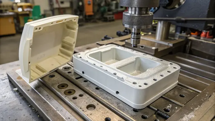
Dealing with undercuts is a fundamental part of designing for manufacturability. It’s a topic that comes up on almost every project I’ve worked on. Understanding your options early in the design process can save you an incredible amount of time and money. It’s the difference between a smooth production run and a project that gets stuck in endless revisions. Let’s break down what these features are and explore the smart ways to manage them.
What is an undercut in injection molding?
You hear the term "undercut" all the time in design meetings, but what does it actually mean for your part? If you misunderstand this concept, you might design a part that simply cannot be made, forcing you back to the drawing board after you thought you were finished. Let’s get a clear, simple definition so you can spot and solve these issues before they become problems.
An undercut is any part of a component that prevents it from being ejected directly from the mold. Imagine the mold opening along a straight line, called the line of draw. Any feature that hooks or hangs in a way that blocks this straight-line exit is an undercut. Common examples include the hooks on snap-fit clips, side holes for buttons, threaded sections for screws, or a simple groove on the side of a part. These features are essential for function but create a manufacturing puzzle.
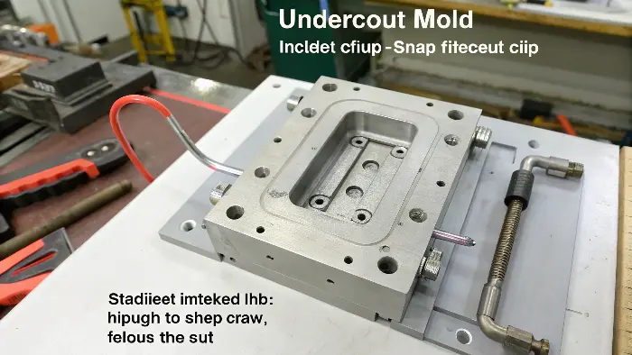
When I first started, I learned about undercuts the hard way. We had a design for a small electronics enclosure with a simple snap-fit clip. The clip worked perfectly in the 3D-printed prototype. But when we sent it for mold manufacturing, the toolmaker called me immediately. He explained that the tiny hook on the clip would lock the part into the mold core. The mold couldn’t open, and the part couldn’t be ejected without breaking it or the mold. That experience taught me a valuable lesson: you have to design not just for the final product, but for the process that creates it.
Understanding the Line of Draw
The line of draw is the direction the two halves of the mold (the core and cavity) separate. It’s also the direction the finished part is pushed out, or ejected, from the mold. For a simple mold, this is a single, straight direction. Any feature on your part must be angled, or drafted, so it doesn’t interfere with this movement. An undercut is a feature that is not parallel to the line of draw and has no draft, creating an obstacle. Think of it like trying to pull a t-shirt with a buttoned cuff straight off your arm without unbuttoning it – the cuff gets stuck.
Common Examples of Undercuts
Undercuts are everywhere in product design because they are incredibly useful. They help parts connect, hold components, and provide key functions. Recognizing them is the first step to managing them.
| Undercut Feature | Common Use | Why it’s an Undercut |
|---|---|---|
| Snap-fit Clip | Securing two parts together (e.g., battery covers) | The hook at the end of the clip faces inward, blocking a straight pull. |
| Side Holes/Windows | Ports for cables, buttons, or ventilation | The hole is perpendicular to the line of draw, creating a hole in the mold steel. |
| Threads (Internal/External) | Screw-in features for caps or fasteners | The helical shape of the thread creates a continuous undercut. |
| Barbs on a Hose Fitting | Creating a secure connection with a hose | The sharp edges face backward, preventing the part from being pulled out. |
| Side-facing Logo/Text | Embossed or debossed branding on the side | The raised or lowered features prevent a clean release from the mold wall. |
Why is avoiding undercuts crucial for simple two-plate molds?
You’re on a tight budget and you want to keep tooling costs low by using a simple, standard two-plate mold. But a single, overlooked undercut in your design can completely ruin that plan. It can make your simple mold unusable, forcing a move to a much more complex and expensive tool. Understanding why undercuts and simple molds don’t mix is the key to designing for cost-effectiveness.
Avoiding undercuts is vital for simple two-plate molds because these molds only open in one direction. An undercut will physically lock the part into one half of the mold, making ejection impossible without damaging the part or the tool. A simple mold has no extra moving parts to release these features. By designing a part without undercuts, you ensure it can be made with the most affordable and reliable type of mold, saving significant time and money on the project.
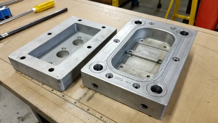
The core principle of a two-plate mold is its simplicity. It has two main parts: the cavity (the "A" side) and the core (the "B" side). When the molding cycle is complete, the press opens, and the two plates separate. Then, ejector pins push the finished part off the core. This entire process happens along one axis, the line of draw. It’s efficient, fast, and low-cost. An undercut completely breaks this simple mechanical process. It acts like an anchor, holding the plastic part firmly in place.
The Mechanics of a Simple Mold
Imagine a plastic cup. It’s a perfect example of a part made for a simple mold. The sides are tapered (drafted), so when the mold opens, the cup slides off the core easily. Now, imagine that same cup has a handle. The handle is an undercut. When the mold tries to open, the core can’t pull straight out of the cup because the handle is in the way. The part is trapped. This is the fundamental conflict between undercuts and simple molds. Forcing the part out would either break the handle or damage the steel mold itself, which is a very expensive repair.
The Cost of Complexity
The moment your design includes a necessary undercut, you leave the world of simple, low-cost tooling. The solution requires adding mechanical components to the mold to deal with the undercut. This immediately increases the cost and complexity of the tool.
| Design Approach | Mold Complexity | Ejection Process | Tooling Cost | Part Cost |
|---|---|---|---|---|
| No Undercut | Simple (Two-Plate) | Straight ejection with pins | Low | Low |
| With Undercut | Complex (Sliders/Lifters) | Side-action mechanism retracts, then ejection | High | Higher (slower cycle time) |
As you can see, avoiding the undercut is the most direct path to lower costs. I always tell designers to treat every undercut as a significant cost adder. Ask yourself: is this feature worth a 30-50% increase in mold cost? Sometimes the answer is yes, but you should always challenge the design first.
How can you avoid undercuts in your injection molding design?
You know undercuts add cost and complexity, but the feature seems essential for your part to work correctly. You feel caught between designing for function and designing for manufacturing. You’re worried you’ll have to compromise the core idea of your product. But before you accept the extra cost, know that there are clever design tricks to eliminate undercuts without sacrificing function.
You can often avoid an undercut by making smart changes to the part geometry. One powerful technique is creating an opening or "pass-through" in the part that allows a section of the mold to shut off against another. This eliminates the trapped steel condition. Another common strategy is to move the mold’s parting line to intersect with the feature, turning it from an undercut into a draftable surface. These design-stage adjustments can completely remove the need for complex mold actions.
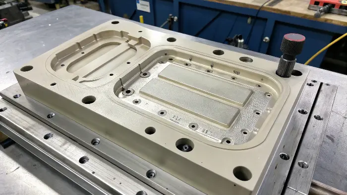
This is where a designer can really show their skill. It’s not just about making something look good; it’s about making it intelligently. I’ve seen brilliant designers save projects tens of thousands of dollars with a few simple tweaks that the client never even noticed on the final product. It’s about thinking like a toolmaker. You have to visualize how the steel of the mold comes together and pulls apart. Once you can do that, you start to see opportunities to design around these challenges.
Redesigning with Shut-Offs
A shut-off is an elegant solution. Let’s go back to the example of a snap-fit clip on the side of a housing. The hook creates an undercut. But what if you add a slot in the main body of the housing, right behind the clip? Now, the part of the mold that forms the hook feature can "pass through" this slot and meet, or "shut off" against, the other half of the mold. When the mold opens, there is no trapped steel. The clip can be formed without needing a complex side-action. This is a very common and effective technique that maintains the function of the clip while simplifying the mold dramatically.
The Power of the Parting Line
The parting line is where the two halves of the mold meet. Its location is one of the most critical decisions in mold design. Sometimes, an undercut exists only because of where the parting line is placed. By moving it, you can change how the feature relates to the line of draw. For example, a feature on the side of a box might be an undercut if the parting line is at the top or bottom edge. But if you move the parting line to run right through the middle of that feature, it’s no longer an undercut. Instead, half the feature is formed in the cavity and half in the core, and both can be drafted for easy release. This requires careful consideration, as it can affect the part’s cosmetic appearance.
What if you absolutely cannot avoid an undercut?
So you’ve tried everything. You’ve looked for ways to redesign the part, you’ve considered moving the parting line, but your part’s function absolutely requires a feature that creates an undercut. You’re worried this is going to make your project too expensive or complex to manufacture. Don’t give up. For these situations, we have standard, reliable mechanical solutions that we build into the mold to handle these necessary features.
When an undercut is unavoidable, the solution is to build action into the mold itself. We use mechanisms like sliders and lifters. Sliders are blocks of steel that move sideways to form and then release the undercut feature before the part is ejected. Lifters are angled components attached to the ejector system. As they push the part up, they also move sideways, releasing internal undercuts. These mechanisms are the key to producing complex plastic parts successfully.
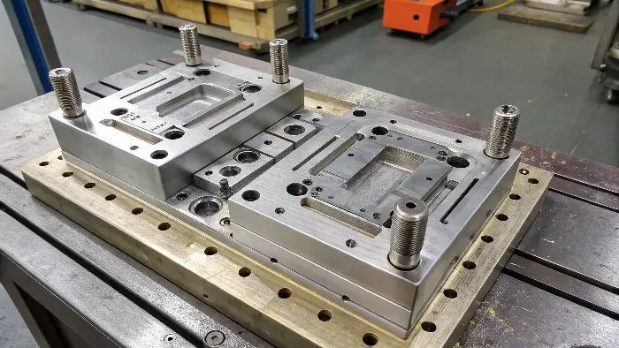
This is where mold making becomes a true craft. Designing these moving components requires precision and experience. While they add to the initial cost of the mold, they are the workhorses that make modern plastic product design possible. From the clips on your phone case to the complex connectors in your car, sliders and lifters are working behind the scenes. My insights from years of building these tools are that you need to choose the right mechanism for the job.
Solving with Sliders
Sliders, also called slides, are the most common solution for external undercuts. Think of a hole on the side of a box. A slider is essentially a moving piece of the mold wall. A steel pin on the slider projects into the mold to create the hole. After the plastic is injected and cools, but before the main mold halves separate, a mechanism pulls the slider and its pin out of the part sideways. With the pin retracted, the undercut feature is gone, and the part can be ejected straight out. Sliders are robust and can form very complex features.
Using Lifters for Internal Undercuts
Lifters are a more subtle solution, often used for undercuts on the inside of a part, where a slider can’t reach. A lifter is a type of ejector that is mounted at an angle. When the ejection system pushes forward, the lifter moves forward and, because of its angle, also moves sideways. This combined vertical and horizontal movement releases the internal undercut as it pushes the part off the core. A common use for lifters is to form the small retaining tabs inside a plastic cap.
| Mechanism | Best For | Direction of Action | Key Consideration |
|---|---|---|---|
| Slider | External features (holes, clips, threads) | Perpendicular to the line of draw | Requires space on the outside of the mold for the mechanism. |
| Lifter | Internal features (tabs, slots, small hooks) | Angled, during the ejection stroke | The feature must have room to be pushed up and out. Limited side travel. |
Material Choice as a Last Resort
In some very specific cases, with a very minor undercut, you can use the material itself as a solution. If the plastic is flexible enough (like TPE or some Polypropylenes), you can sometimes design the part to be "stripped" from the mold. This means the flexible material bends or stretches just enough to pop over the small undercut during ejection. This is risky and requires careful design and material selection, but for the right application, it can be a clever way to avoid mechanical actions.
Conclusion
In the end, dealing with undercuts is a core skill in product design and manufacturing. The best approach is always to try and design them out first to keep your mold simple and your costs low. But when a feature is essential for function, don’t see it as a roadblock. Instead, see it as a solvable challenge. By using proven mold technologies like sliders and lifters, we can manufacture almost any design you can imagine.
