Designing a great product is one thing, but turning it into a physical reality through injection molding can feel like a black box. You know the basics, but do you truly grasp the intricate dance of heat, pressure, and mechanics happening inside the mold? Misunderstanding this process can lead to costly defects, delays, and frustrating redesigns. Let’s pull back the curtain and demystify the entire process, step-by-step, so you can design with more confidence and precision.
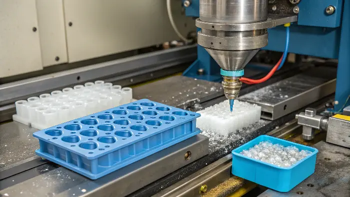
A plastic injection mold works by injecting molten plastic into a precisely machined cavity under high pressure. First, plastic pellets are melted and forced into the mold, which is clamped shut. The mold contains the negative space of the desired part. The plastic then cools and solidifies inside this cavity, taking its shape. Finally, the mold opens, and an ejection system pushes the finished part out. This cycle repeats rapidly, allowing for the mass production of identical plastic parts with high precision.
That’s the high-level view. It sounds simple enough, right? But as any experienced designer knows, the real magic—and the source of many challenges—lies in how each stage is controlled and executed. To truly master mold design, you need to understand the "why" behind each step. I’ve spent my entire career in this industry, from the factory floor to running my own company, and I’ve learned that a deep understanding of the fundamentals is what separates good designers from great ones. Let’s break down the core principles and mechanisms that make it all happen.
What is the principle of injection molding?
You know the terms: clamping, injection, cooling, and ejection. But do you understand the underlying physics that govern the entire process? Without a firm grasp of these principles, you’re essentially guessing when troubleshooting issues like sink marks or short shots. It feels like trying to solve a puzzle with missing pieces. Let’s clarify the core scientific principles. Understanding the relationship between pressure, temperature, and time is the key to unlocking consistent, high-quality production.
The core principle of injection molding is the controlled transformation of a solid thermoplastic material into a liquid, then back into a solid within a specific shape. This is achieved through a cycle of heating, injecting, packing, and cooling under precise pressure. The process leverages the properties of polymers, which can be melted and solidified repeatedly without significant degradation. It’s a game of managing heat transfer and fluid dynamics to perfectly replicate the mold’s geometry in a repeatable, efficient cycle.
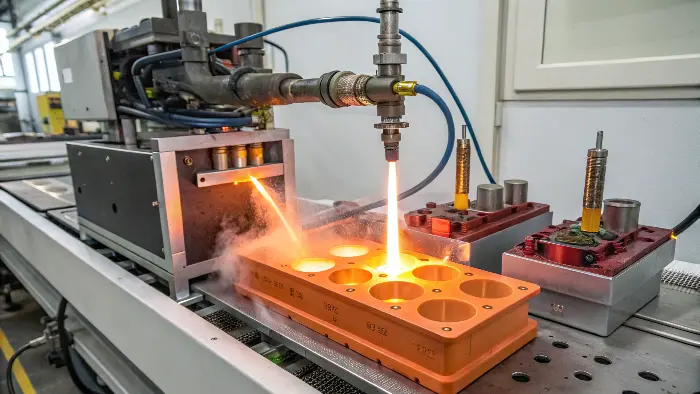
To really get it, you have to think of the process as a carefully choreographed sequence. I remember early in my career, we struggled with a part that had terrible sink marks. We kept increasing the injection pressure, but the problem persisted. It wasn’t until an old-timer pointed out our cooling time was too short and the packing pressure was dropping off too early that we solved it. It was a classic lesson in understanding the entire principle, not just one part of it. The process isn’t just one action; it’s a cycle of distinct phases.
The Four Key Phases of the Molding Cycle
Each phase has a specific job, and they all depend on each other. If you get one wrong, the others will suffer.
| Phase | Primary Goal | Key Parameters |
|---|---|---|
| Clamping | Securely close and hold the mold against injection forces. | Clamping Tonnage |
| Injection & Packing | Fill the mold cavity and apply pressure to compensate for shrinkage. | Injection Speed, Pressure, Time |
| Cooling | Solidify the plastic part inside the mold. | Cooling Time, Coolant Temperature |
| Ejection | Open the mold and safely remove the finished part. | Ejection Speed, Stroke |
The entire principle hinges on the interplay of Pressure, Temperature, and Time. You need enough heat to melt the plastic into a consistent fluid. You need immense pressure to force that fluid into every tiny detail of the mold cavity. Then, you need to hold that pressure (the packing phase) while the part cools to prevent voids or sink marks as the material shrinks. Finally, you need enough time for the part to cool and become solid enough to be ejected without deforming. Mastering this balance is the true art of injection molding.
How is plastic melted in injection molding?
You feed solid plastic pellets into a machine, and molten plastic comes out the other end. It seems like simple heating, right? But if you assume it’s just like melting butter in a pan, you’ll miss the crucial role of friction and shear. This misunderstanding can lead to material degradation or inconsistent melt flow, which can ruin your parts. Let’s look inside the barrel and see exactly how those pellets are transformed into a homogenous, injectable melt.
Plastic is melted in an injection molding machine through a combination of conduction and friction. As plastic pellets travel from the hopper down the barrel, heater bands on the outside provide conductive heat. More importantly, the rotation of the reciprocating screw generates intense friction and shear forces. This shearing action is the primary source of heat, ensuring the plastic is melted uniformly and thoroughly into a consistent, homogenous fluid ready for injection.
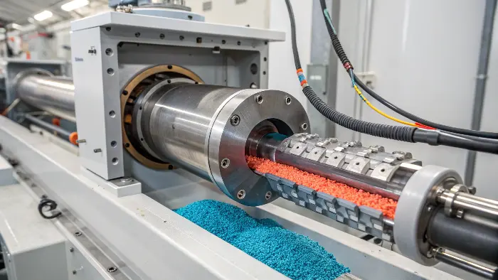
The real workhorse for melting plastic is the reciprocating screw. It’s a brilliant piece of engineering. Many designers I talk to are surprised to learn that up to 80% of the melting energy can come from the screw’s mechanical action, not the external heaters. The heaters are more for getting the process started and maintaining a stable temperature along the barrel. Understanding this helps you appreciate why screw design and rotation speed are so critical for different types of plastics. The journey from a solid pellet to a perfect liquid melt all happens within the confines of the barrel, thanks to the screw.
The Journey from Pellet to Melt
The screw isn’t just a simple rod. It’s designed with changing geometry to process the plastic in stages. As the screw rotates, it carries the plastic pellets forward through three distinct zones.
| Screw Zone | Description | Primary Function |
|---|---|---|
| Feed Zone | Deep flights at the rear of the screw. | Transports solid pellets from the hopper into the barrel. |
| Transition Zone | The screw root diameter increases, and flight depth decreases. | Compresses the material, generating intense shear and friction. This is where most of the melting occurs. |
| Metering Zone | Shallow flights at the front of the screw. | Homogenizes the melt, ensuring it’s at a uniform temperature and consistency before injection. |
As the screw turns, it pulls pellets from the hopper into the feed zone. In the transition zone, the channel gets shallower, squeezing the pellets against the barrel wall. This compression and the friction from the screw’s rotation create immense shear forces, which heats the plastic from the inside out. This is far more efficient and consistent than just relying on external heat. By the time the plastic reaches the metering zone, it’s a fully homogenized melt, ready at the front of the barrel for the injection shot.
What is the mechanism of plastic injection molding?
You understand the principles and how the plastic melts. But how does the machine itself execute these steps with such force and precision? Without knowing the mechanics, you can’t fully appreciate the design constraints. Why are draft angles so important? Why is clamping force a critical spec? The machine’s physical actions dictate these design rules. Let’s examine the two main mechanical systems at play: the injection unit and the clamping unit.
The mechanism of plastic injection molding involves two primary systems working in sync: the injection unit and the clamping unit. The injection unit is responsible for melting and injecting the plastic using a reciprocating screw. The clamping unit holds the two halves of the mold together with immense force, resists the pressure of the injected plastic, and then opens the mold to eject the finished part. The precise coordination of these hydraulic or electric mechanisms defines the molding cycle.
I once saw a new operator set the clamping force too low for a large part. During injection, the pressure from the molten plastic forced the mold halves slightly apart. The result was ‘flash’—a thin sheet of plastic leaking out of the parting line. It was a messy, expensive lesson in how powerful these mechanisms are and why the clamping force must always be greater than the injection pressure inside the mold. These two units are the muscle of the entire operation.
The Machine’s Two Halves
Think of the injection molding machine as having two distinct jobs, handled by two systems.
| Mechanical Unit | Key Components | Primary Actions |
|---|---|---|
| Injection Unit | Hopper, Barrel, Reciprocating Screw, Heaters, Nozzle | 1. Rotates the screw to melt and prepare plastic (plasticizing). 2. Moves the screw forward like a plunger to inject the melt. |
| Clamping Unit | Platens (Stationary & Moving), Tie Bars, Ejection System | 1. Closes the mold. 2. Applies and holds clamping force (tonnage). 3. Opens the mold. 4. Activates ejectors to remove the part. |
The Injection Unit in Action: The reciprocating screw is the star here. First, it rotates to plasticize the material, as we discussed. As it does this, it moves backward, allowing a "shot" of molten plastic to accumulate in front of it. When it’s time to inject, the screw stops rotating and is pushed forward by a powerful hydraulic or electric system. It acts like a plunger, forcing the accumulated melt through the nozzle and into the mold.
The Clamping Unit’s Critical Role: This unit is all about force. Its job is to hold the mold shut against the incredible pressure of injection, which can be thousands of PSI. This force, called clamping force, is measured in tons. A machine might be rated as a "200-ton" machine, meaning it can apply 200 tons of force to keep the mold closed. After the part cools, the clamping unit opens the moving platen, separating the mold halves and activating the ejection system to push the part out.
How do plastic molds work?
The machine is the muscle, but the mold is the heart of the operation. It’s a complex piece of steel tooling, and it’s where your design truly comes to life. If your design doesn’t account for the mold’s internal workings—gates, runners, cooling channels, ejector pins—it’s destined to fail. A beautiful part design is useless if it can’t be molded effectively. Let’s open up the mold and explore the critical components that shape the plastic and ensure a clean release.
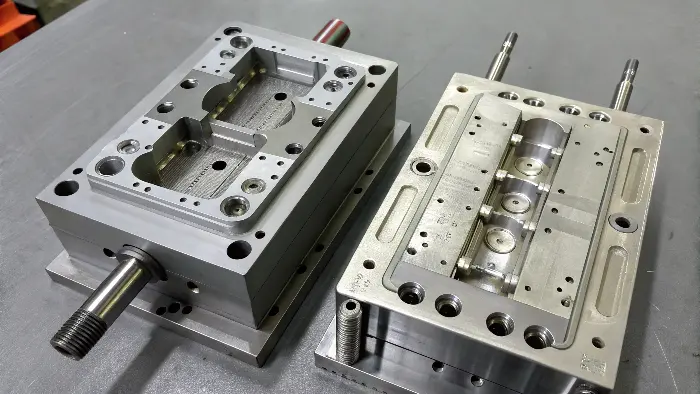
A plastic mold works by providing a precisely shaped cavity for molten plastic to fill and solidify. It consists of two main halves: the "A" side (cavity half), which attaches to the stationary platen, and the "B" side (core half), which attaches to the moving platen. The mold includes a runner system to guide plastic to the cavity, cooling channels to regulate temperature, and an ejection system (ejector pins) to push the finished part out once it has cooled and the mold opens.
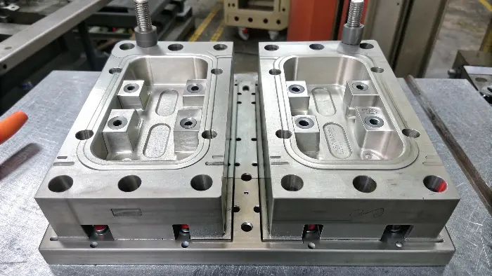
The mold is where the magic happens, and it’s where most of the upfront investment goes. As a designer, understanding its anatomy is not optional; it’s essential. Every feature you design on a part has a corresponding feature that must be machined into the mold steel. Thinking about how the mold opens, how the plastic flows, and how the part will be pushed out should be part of your design process from the very beginning. This is how you design for manufacturability.
The Anatomy of a Mold
A mold is much more than just a hollowed-out block of steel. It’s a sophisticated tool with several integrated systems.
| Mold Component | Location / Description | Function |
|---|---|---|
| Cavity (A-Side) | The "female" half, attached to the stationary platen. | Forms the external, often cosmetic, surface of the part. The nozzle of the machine injects plastic into this side. |
| Core (B-Side) | The "male" half, attached to the moving platen. | Forms the internal, often structural, features of the part. The part shrinks onto and sticks to the core as it cools. |
| Runner System | Channels machined into the mold face. | Guides the molten plastic from the sprue (main entry point) to the gates (part entry points). |
| Cooling System | A network of channels drilled through the mold. | Circulates water or oil to control the mold temperature and cool the plastic part efficiently. |
| Ejection System | Pins and mechanisms located in the core half. | Pushes the solidified part off the core after the mold opens. This is why draft angles are critical. |
When the mold closes, the core and cavity meet to form the empty space that will become your part. Molten plastic flows from the machine’s nozzle, through the sprue, down the runners, and through the gates to fill this space. All the while, coolant is circulating through the channels, pulling heat out of the plastic. Cooling is often the longest part of the cycle, so an efficient cooling design is vital for profitability. Once the part is solid, the mold opens, and the ejection system pushes the part off the core. Every single one of these components must work perfectly, thousands of times, to produce consistent parts.
Conclusion
So, how does a plastic injection mold work? It’s a precise cycle where a machine melts plastic and a mold gives it shape. The process relies on the core principles of heat and pressure, executed by the machine’s injection and clamping units. The mold itself, with its cavity, core, runners, and cooling systems, is the heart of the operation. Understanding how all these elements work together is the key to designing better, more manufacturable parts.
