
Injection molding optimization is a controlled study of inputs and outputs against defined quality and capacity requirements. The objective is a robust operating window, not an unexplained “sweet spot” or the shortest possible cycle.
Injection molding process optimization is the work of increasing quality, output or cost performance without losing the stable process window. It should begin with a defined baseline and critical characteristics, then use structured trials and production data to separate material, machine, mold, method, measurement and handling effects.
Related CKMOLD resources: production injection molding, mold testing and validation, DFM analysis.

What Does Injection Molding Process Optimization Mean?
Optimization means finding and controlling a process window that meets quality and capacity requirements with acceptable risk—not merely reducing cycle time or defects in one trial. Define critical-to-quality outputs and constraints before changing settings.
Separate inputs (material, tool, machine, environment and settings) from outputs (part weight, dimensions, appearance, strength, pressure traces, cycle and accepted yield). Optimize only after the measurement system and baseline are repeatable. For symptom-specific evidence, use the guides to distinguishing bubbles from voids and diagnosing bent or warped parts before selecting variables to change.
Primary sources checked: Autodesk — DOE Quality Criteria (optimization objectives and machine-limit context); Autodesk — Cycle Time (fill, pack, cool and mold-open stage definitions). The cited scope still has to be matched to the exact grade, tool, product and destination market.

Which Variables Should Be Studied?
There is no universal list of eight independent settings. Organize variables by mechanism:
- material: exact grade/lot, moisture, regrind and contamination;
- thermal: actual melt, mold/coolant and residence history;
- fill: velocity profile, pressure demand and transfer;
- pack: hold pressure/time, gate seal, cushion and check-ring repeatability;
- cool/eject: cooling balance, ejection temperature, opening/ejection and handling;
- tool/machine: vents, gates, cooling, wear, calibration and capability.
Change controllable inputs deliberately and monitor side effects; many variables interact.
A Data-Driven Optimization Sequence
- freeze drawing, material, tool and measurement revisions;
- define CTQs, defect limits, capacity target and machine/tool constraints;
- stabilize material handling, tool temperature, machine condition and baseline;
- characterize fill and transfer, then pack/gate seal, then cooling/ejection;
- use a designed experiment where interactions matter and sufficient data can be collected;
- challenge the proposed window at controlled edges and confirm capability;
- document setup, alarms, reaction plan, maintenance and change control.
This is a general engineering sequence, not a claim that one eight-step recipe fits every process.

How Can Cycle Time Be Reduced Without Hiding Quality Loss?
Measure the full cycle: close/protect, fill, pack, cool/recover, open, eject and handling. Address the largest verified constraint. Examples include cooling balance, unnecessary hold beyond gate seal, slow recovery, robot motion or excessive open time—but only after confirming part dimensions, appearance, function, residual stress and stable ejection.
Theoretical output is cavities × 3600 ÷ cycle seconds. Accepted output also depends on uptime and yield. Report both assumptions; a faster nominal cycle can increase accepted-part cost if scrap, inspection or maintenance rises.

Which KPIs Show a Better Process?
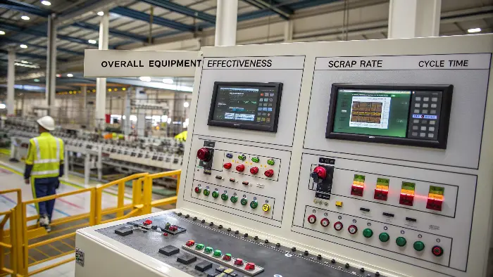
Use a balanced set: first-pass accepted yield, defect mode/rate, critical-dimension capability, process-trace stability, cycle breakdown, downtime/reason, material loss and accepted output. OEE can combine availability, performance and quality, but labels and planned-time rules must be defined consistently. A “world-class” percentage is not evidence that a specific molding process is capable.

Define the Objective and Baseline
Choose the target: less scrap, shorter cycle, lower energy, tighter dimensions, better appearance, more output or fewer maintenance interruptions. Record material, mold, machine, process, inspection, cycle, weight and defect baseline before changing anything.
Stabilize Material, Mold and Machine First
Verify resin grade, drying, color, regrind, temperature control, cooling flow, vents, gates, ejection, nozzle, screw, pressure and calibration. Optimization built on a leaking cooling circuit or wet resin is not a reliable improvement.
For production monitoring, the smart injection-molding controls guide separates useful process signals from product acceptance. For tool decisions that affect accepted output, review the cycle-efficiency and part-quality mold engineering guide.
Optimize Fill, Pack and Cool in Sequence
Use fill studies and speed profiles to establish flow, then determine pressure and holding from weight and gate freeze, and finally reduce cooling only while dimensions and shape remain stable. Changing all stages at once makes the result hard to explain.
Use DOE or Capability Data for Interactions
Some variables interact: mold temperature and cooling, speed and shear, pressure and flash, material moisture and strength. A designed experiment or controlled matrix can reveal a robust region rather than a fragile best point.
Lock the Result and Monitor Drift
Document process window, alarms, inspection, startup, changeover, maintenance and escalation. Trend critical dimensions, weight, cycle, pressure, temperature and scrap so the team sees drift before it becomes a customer issue.
Optimize an Injection Molding Process: Buyer Review Checklist
- Define optimization target, critical characteristics and a verified process baseline.
- Stabilize resin, drying, color, cooling, vents, mold, machine and measurement first.
- Optimize fill, pack and cooling in a sequence that preserves cause and effect.
- Use structured trials or DOE to identify interactions and a robust process region.
- Lock settings, alarms, inspection, maintenance and trend monitoring after approval.
FAQ
What should be optimized first in injection molding?
Stabilize material, mold, machine and measurement, then optimize filling, packing, cooling and handling against the defined objective.
How do I know an optimized cycle is really better?
Confirm repeatability, quality, capability, energy or cost over enough cycles and conditions—not only one fast cycle.
Conclusion
Optimize in a quality-first order: define CTQs, stabilize inputs, characterize fill/pack/cool, study interactions, confirm a robust window and lock the result with monitoring and reaction plans. Judge improvements by accepted parts and capability, not isolated settings or a single headline KPI.