
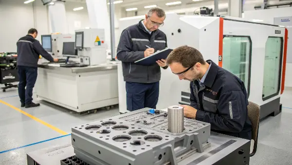
Cycle efficiency and part quality are co-optimized before steel by defining CTQs, material, machine limits, feed, cooling, venting, ejection, handling and acceptance. The shortest nominal cycle is not the objective if it reduces capability or tool reliability.
Cycle efficiency and part quality are not opposing goals when the mold is engineered as a complete production system. A fast cycle that creates unstable dimensions is not efficient, and a suitable part that requires excessive manual handling is not a robust production solution. Effective mold engineering connects flow, cooling, ejection, machine capability, automation and maintenance from the beginning.
Related CKMOLD resources: mold design services, production injection molding, multi-cavity molds.
Efficient tool design aligns DFM, exact material, feed, cooling, ejection, machine/automation limits and validation around accepted output. Gate or steel optimization alone cannot guarantee the shortest cycle, zero defects or immediate return on investment; compare measured yield, cycle stages, labor, downtime and maintenance against the approved CTQs.

The engineering process should be reviewable rather than attributed to unverified years of company experience. Ask for the decision trail from requirements and DFM through simulations or calculations, tool drawings, trial changes, approved window, CTQ evidence and production controls.
We’ll start with the foundation of every successful project.
What is the concept of Mould design?
Do you view a mold as just a shaped block of steel? This common misconception can be costly. A poor mold design leads to endless headaches, including part defects, slow production speeds, and frequent tool repairs, all of which drain your budget and delay your timelines. Understanding the core concept of mold design reveals it’s a detailed engineering blueprint for manufacturing success.
Mold design is the comprehensive engineering process of creating a detailed blueprint for a tool that shapes plastic parts through injection molding. It’s much more than just the cavity’s shape. It involves selecting the right materials, designing the feed system (sprue, runners, gates), planning the cooling channels, creating an ejection mechanism, and ensuring the mold’s structural integrity. A great design reliably balances part quality, production speed, and tool longevity to meet your specific project goals.

Core and Cavity: The Heart of the Mold
The core and cavity are the two halves of the mold that come together to form the shape of your part. The “cavity” is the fixed half and typically forms the exterior, or “A-side,” of the component—the side you usually see. The “core” is the moving half and forms the interior, or “B-side.” The precision here is everything. We engineer these surfaces with exact tolerances, specific surface finishes, and calculated draft angles (slight tapers) to ensure the part not only looks suitable but also releases from the mold easily without damage.
The Feed System: Guiding the Plastic
The feed system is the network of channels that guides the molten plastic from the injection molding machine’s nozzle into the cavity. It consists of:
- Sprue: The main channel where plastic first enters the mold.
- Runners: Smaller channels that branch off the sprue to lead plastic toward the part cavities.
- Gates: The final, narrow opening through which the plastic enters the cavity. The type and location of the gate are critical for controlling how the part fills.
| Gate Type | Description | Best For |
|---|---|---|
| Edge Gate | Located on the parting line of the mold. Simple and cost-effective. | Flat, simple parts. |
| Submarine Gate | Ejects automatically, cutting the runner from the part. | High-volume production, small parts. |
| Hot Tip Gate | Part of a hot runner system, injects plastic directly into the part. | Eliminating runner waste, large parts. |
How Should Cooling Be Engineered and Validated?
Cooling often occupies much of the cycle, but the controlling point may be a local hot spot, part stiffness at ejection, crystallization, dimensional stability or another stage. Design circuits from heat load, channel access, flow/pressure drop, steel around the cavity and maintenance—not from a universal cycle-reduction percentage.
Conventional drilled circuits, baffles, bubblers, high-conductivity inserts and conformal channels have different cost, service and geometry limits. Autodesk’s public fill/pack/cool process description separates cooling from filling and packing controls; simulation can compare thermal alternatives, but T1 surface-temperature, flow, pressure-drop, cycle and dimensional evidence must confirm the design.
| Cooling decision | Evidence before steel | T1 evidence |
|---|---|---|
| circuit layout | distance/steel support, flow path and correction access | flow/leak and cavity-surface temperature map |
| ejection temperature | material/geometry stiffness basis | part temperature, force, marks and deformation |
| cycle proposal | stage-time and bottleneck assumptions | accepted dimensions/appearance/function across the window |

How Should Manufacturing Quality Be Controlled?
Quality controls must be defined in the project control plan. Connect each CTQ to its material or process input, measurement method, frequency or sampling rationale, reaction plan and retained record. DFM and simulation reduce design risk but do not prove a defect-free process.
Before production, approve the exact resin/color/additive, tool revision, machine/setup, measurement system, representative sample and process window. During production, monitor the variables and product characteristics that have a demonstrated relationship to risk; contain and investigate deviations before release.

Evaluate the Supplier’s Closed-Loop Quality System
Process control, product verification, nonconformance/corrective action and supplier/material control are useful functions, but their labels do not prove performance. Ask how the supplier applies each function to this part.
| Function | Project-specific evidence |
|---|---|
| process control | approved window, monitored variables, limits and reaction plan |
| product verification | CTQ list, method, cavity/sampling coverage, measurement capability and report |
| nonconformance/corrective action | containment, cause evidence, action verification and recurrence monitoring |
| material/supplier control | exact specification, traceability, incoming evidence and change notification |
Do not assume every new tool requires every drawing dimension on one report, hourly checks, an AQL final inspection or a certificate for every resin batch. Define the appropriate scope contractually from risk and customer requirements.

Release Production From Evidence, Not a Golden Sample Alone
A golden sample supports appearance or comparison only within a controlled revision and condition. Production release should also identify the material, tool/cavity, machine/setup, process window, CTQ results, measurement conditions and approved deviations.
Use first-off, in-process and final verification according to the control plan. Record actual results and reaction to trends; “locked settings” do not prevent variation in material, environment, machine response, tool condition or measurement.

Optimize Accepted Output, Not Cycle Time in Isolation
Compare accepted parts per scheduled hour after startup scrap, cavity imbalance, stops, rework and planned maintenance. A faster cycle is beneficial only when CTQs remain capable and the tool, automation and cooling system remain serviceable. State the approved window and the evidence needed before changing it.
Set the Production Objective
Define annual volume, target cycle, cavity count, machine, critical dimensions, surface, acceptable scrap and maintenance expectation. This prevents the design from optimizing an isolated feature while missing the actual capacity or quality requirement.
Balance Filling and Packing
Gate, runner, cavity layout, venting and material choice should create a predictable fill sequence. Balanced filling reduces cavity-to-cavity variation and makes packing and process monitoring more useful. Family molds require an explicit decision about whether all parts can share a stable process window.
Design Cooling Around the Bottleneck
The thickest or hottest region often determines cycle time and deformation. Independent circuits, suitable flow, inserts, baffles or other thermal strategies can remove heat more effectively than adding time to the whole cycle. Cooling must remain accessible for cleaning and measurement.
Make Ejection and Automation Part of the Quality Plan
Balanced ejectors, draft, lifters, slides, robots and part handling protect the released shape. Automation should not pull, drop or fixture a part before it has enough stiffness. Define how parts are oriented, inspected, separated and transferred at production speed.
Use Trials to Optimize the Whole System
Trial data should include fill, pressure, cycle, cooling, cavity weights, critical dimensions, appearance, ejection and handling. A cycle reduction is acceptable only if the process window and inspection result remain stable over repeat runs.
Engineer Injection Molds for Cycle Efficiency and Part Quality: Buyer Review Checklist
- Set volume, cycle, cavity, machine, quality, scrap and maintenance objectives before design.
- Balance gate, runner, venting, cavity layout, packing and material behavior.
- Design cooling around hot spots and the cycle bottleneck with measurable circuits.
- Integrate ejection, robots, inspection and handling without distorting warm parts.
- Approve efficiency gains only after repeat trials prove quality and process stability.
FAQ
What usually limits injection mold cycle time?
Part cooling often dominates, but gate freeze, material preparation, ejection, handling, mold temperature and inspection can also limit the usable cycle.
Can adding cavities generally improve efficiency?
Only when the machine, flow balance, cooling, inspection and maintenance capacity support the added cavities.
Conclusion
Efficient molds are designed around accepted output: balanced filling and packing, controlled thermal bottlenecks, reliable release/automation, maintainability and a project-specific quality plan. Confirm the proposal with structured trials and measured part evidence before production release.