
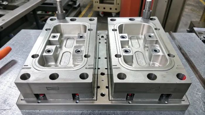
Quick answer: During each shot, the mold aligns and seals, routes melt while venting air, transmits packing pressure, removes heat, moves undercut features, opens and ejects the part before returning safely. Every stage prepares the boundary condition for the next one.
Close, Align and Protect
Guide components bring mold halves together; parting surfaces, interlocks and support establish final alignment under load. Slides and cores must be home, ejectors returned and no part or runner left between steel. Low-force mold protection should recognize abnormal resistance before full clamp.
Clamp force then resists opening caused by cavity pressure. Correct fitting and structural support remain essential; tonnage cannot repair a damaged parting line.
Receive Melt and Move Air
The nozzle seals to the sprue or hot-runner interface. Runners and gates divide the melt among cavities and shape its direction and speed. As melt advances, air leaves through parting vents, inserts, ejector clearances or designed overflows.
Gate, vent and cavity conditions interact. A blocked vent can increase pressure and burns; an eroded gate can change balance; a leaking nozzle can disturb shot consistency.
Process Control Map
| Cycle stage | Tool function | Typical tool-related risk |
|---|---|---|
| Close/clamp | Align, interlock, support and seal parting | Mismatch, flash, trapped part or action not home |
| Fill/vent | Distribute melt and release gas | Imbalance, burn, short shot, jetting or weld line |
| Pack/cool | Transmit pressure and remove heat | Sink, stress, hot spots, warp or long cycle |
| Open/eject | Release actions and support the warm part | Scuff, pin mark, deformation or mold damage |
Transmit Packing Pressure
After volumetric fill, the still-open gate connects holding pressure to the shrinking melt. Tool steel and support resist the load while vents must not flash. Gate size and freeze determine how long downstream regions can gain mass.
Cavity or part-weight evidence helps reveal whether pressure reaches CTQs. Excess packing can stress the part or mold; insufficient packing can leave sink or dimensional loss.
Remove Heat and Set Shape
Cooling circuits carry heat through cavity steel to the temperature-control medium. Geometry, inserts, actions and circuit flow create local thermal patterns. The part solidifies from the surface inward and develops shrinkage and orientation.
The slowest zone often determines ejection time. A stable controller does not support equal cavity surfaces, so circuit flow and representative temperature should be maintained.
Move Actions and Open
Slides, lifters, unscrewing or hydraulic cores release undercuts in a defined sequence. Wedges and locks unload before motion; sensors confirm position. The clamp then opens far enough for safe part and runner removal.
Stroke should be no greater than needed, but clearance and deceleration must protect the mold, part and robot. Wear or lubrication changes can shift timing and dimensional repeatability.
Eject, Handle and Reset
Pins, sleeves, strippers or air assist distribute force against a warm part that grips cores through shrinkage and texture. Draft, polish and cooling set release demand. Robot or operator handling must avoid bending or scratching the part.
Ejectors and actions return, sensors confirm home and the cavity is checked before the next close. Stable production depends on repeating these transitions without hidden intervention.
Process Control Checklist
- Verify actions home, ejectors returned and cavity clear before close.
- Maintain parting fit, interlocks, support and mold protection.
- Inspect nozzle, runner, gates and cavity balance.
- Keep vents clean and accessible at actual end-of-fill regions.
- Confirm gate seal, support and packing response.
- Control circuit flow, surface temperature and slow thermal zones.
- Sequence actions, opening, ejector and robot safely.
- Monitor repeated transitions, wear, lubrication and intervention.
Illustrative Stage Interaction
Illustrative engineering example—not a claimed CKMOLD customer result: A part begins showing deep ejector marks after cycle time is reduced. The mold still fills correctly, but the core remains hotter and the part has lower stiffness at ejection. The correction evaluates cooling and release state rather than increasing ejector force.
Implementation Questions
When does the mold vent air?
Air is displaced throughout filling, especially near end-of-fill and around meeting flow fronts, through designed vent paths.
What happens during packing?
Holding pressure adds material through the gate while regions remain connected, compensating some volumetric shrinkage.
Why can opening or ejection damage a good part?
The part may lack stiffness, grip the core, contact an undercut or receive concentrated force or poor handling.
What resets before the next cycle?
Ejectors and actions return, sensors confirm home and the cavity must be clear before protected closing.
Implementation Resources
Apply the Inside a Production Mold Cycle review to your released design. Share the function, exact resin, annual volume, CTQs, cosmetic limits and launch timing through the CKMOLD project form. If CAD is relevant, send it directly to jerry@ckmold.com; the form does not require an upload.