Insert molding part design does not have to be difficult. If you let critical design details slide, you’ll experience poor bonds, broken inserts, or too much scrap. These problems lead to costly rework, lost production schedules, and field failures, which damage your reputation. I’m here to guide you through the critical design considerations that will allow you to produce successful insert molded products from the start.
Successful insert molding relies on a well-conceived plan for the insert itself, insert and plastic material compatibility, mold design (gates and runners) to ensure that the insert is maintained, and integration of features to hold the insert firmly in place both in and out of the molding process. Whatever these factors are, they need to be resolved prior to starting to prevent costly errors and result in strong, reliable finished products.
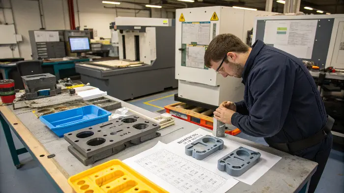
Getting these design components just right is essential. It’s not just about makinMaking the part function dependably is more important than making it look good. and efficiently. I’ve seen many projects at CKMOLD where a little extra thought in the design phase saved a lot of headaches down the line. Let’s explore these critical considerations in more detail.
How Does Proper Insert Design Itself Impact Moldability and Part Strength?
You’ve selected an insert, but have you given its form and characteristics enough consideration? A poorly designed insert can make molding difficult or result in a weak final partThis may cause the inserts to break, move while being molded, or not bond properly.ith the plastic, ultimately compromising your product’s integrity. Together, we will examine how careful insert design can greatly enhance the manufacturing process and the final product’s strength.
Successful insert design involves the design of features that assist in its secure positioning and retention in the mold, assist in smooth plastic flow past it, and produce good mechanical interlocks with the plastic. Features like knurls, grooves, undercuts, or through-holes on the insert are not trappings; they play a critical role in preventing the insert from shifting, rotating, or pulling out, thereby leading to a strong and durable assembly.
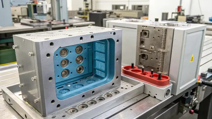
We frequently dedicate a significant amount of time solely to the insert design when I work with clients like Jacky, a product and mold designer. It’s that important.
Think about these aspects for your insert:
- Mechanical Interlocks: These are your best friends for a strong bond.
- Knurls: Rough, patterned surfaces that give the plastic something to grip.
- Grooves/Undercuts: Channels or indentations that the plastic flows into, creating a physical lock.
- Through-holes: Holes in the insert allow plastic to flow through, creating a very strong connection, almost like a rivet.
- Shoulders/Flanges: These can help position the insert and provide a surface for the plastic to press against, preventing pull-out.
- Orientation and Placement Features: How will the insert be loaded into the mold?
- Flats or Asymmetrical Shapes: These can prevent the insert from rotating and ensure it’s placed in the correct orientation, especially important for automated loading.
- Avoid Sharp Corners: The plastic molded around the insert may develop stress points due to sharp internal corners, which could result in cracks. Try to include radii where possible.
- Material and Surface Finish: The insert material itself and its surface texture can influence how well the plastic adheres. A slightly rougher surface might be better than a highly polished one for some plastic-insert combinations.
- Tolerances: The insert needs to fit snugly in the mold cavity. If it’s too loose, it can shift. It may become stuck or harm the mold if it is too tight.
I recall working on a project that used a brass threaded insert. The initial design was just a smooth cylinder. We had issues with the insert spinning when a screw was tightened. We added a simple knurl pattern and a small annular groove. That small change made a huge difference in the torque resistance.
Key Insert Design Features and Their Purpose
| Insert Feature | Purpose |
|---|---|
| Knurling | Increases surface area and provides grip for anti-rotation and pull-out resistance. |
| Grooves/Undercuts | Create mechanical locks when plastic flows into them. |
| Through-holes | Allow plastic to flow through, forming a strong mechanical anchor. |
| Shoulders/Flanges | Help with positioning, prevent push-through, and resist pull-out forces. |
| Flats/Keyways | Ensure correct orientation and prevent rotation. |
| Radiused Edges | Reduce stress concentration in the surrounding plastic. |
What Role Does Material Selection Play for Both the Insert and the Plastic?
Selecting materials for your insert and the surrounding plastic may seem simple, but a mismatch can lead to serious issues. Incompatible materials can lead to poor adhesion, cracking due to different shrinkage rates, or even chemical degradation, dooming your part. Achieving a long-lasting and useful insert molded product requires an understanding of proper material selection and pairing.
Material selection is critical. The insert material must withstand molding temperatures and pressures, while the plastic must be compatible with the insert for good adhesion and have appropriate flow characteristics. In order to avoid stress, cracking, or delamination after molding, it is also necessary to control the differences in the thermal expansion coefficients of the plastic and the insert.
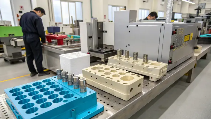
This is a conversation I have almost daily. For the plastic resin, you need to consider:
- Melt Flow Index (MFI): A higher MFI means the plastic flows more easily, which can be good for filling around complex inserts, but too high might lead to flashing.
- Shrinkage Rate: All plastics shrink as they cool. If the plastic shrinks too much around a rigid insert, it can cause high stress or even crack the plastic.
- Mechanical Properties: Strength, stiffness, impact resistance – these need to match the application.
- Thermal Properties: Can it withstand the operating temperatures of the final product?
- Adhesion Characteristics: Some plastics bond better to metals or other materials than others.
For the insert material (often metal, but can be ceramic or another plastic):
- Strength and Stiffness: It must withstand the injection pressure without deforming.
- Thermal Conductivity: High thermal conductivity can help the insert cool faster, but it can also create a cold spot that affects plastic flow if not managed.
- Corrosion Resistance: Important if the part will be exposed to moisture or chemicals.
- Coefficient of Thermal Expansion (CTE): This is a big one. If the CTE of the insert and the plastic are very different, temperature changes can cause stress at the interface. For example, metals generally expand less than plastics.
I worked on a component that had a polycarbonate housing with a steel insert molded into it. The initial design didn’t account for the CTE difference. When the parts went through temperature cycling tests, we saw tiny cracks forming around the insert. We had to adjust the plastic material to one with a CTE closer to steel and also add some design features to allow for slight movement. Pre-heating inserts can sometimes help by reducing the temperature difference during molding, which can improve flow and reduce stress.
Material Property Considerations for Insert Molding
| Property Category | Plastic Resin Considerations | Insert Material Considerations |
|---|---|---|
| Mechanical | Tensile strength, impact resistance, flexural modulus. | Yield strength, hardness, resistance to deformation. |
| Thermal | Melt temperature, heat deflection temperature, shrinkage rate. | Melting point, thermal conductivity, CTE. |
| Flow/Processing | Melt Flow Index (MFI), viscosity. | N/A (but surface finish can affect plastic flow over it). |
| Compatibility/Adhesion | Chemical compatibility with insert, potential for bonding. | Surface energy, potential for chemical/mechanical bonding. |
Why is Strategic Gate Location and Runner Design Crucial for Insert Molding?
Your design may succeed or fail based on how the plastic enters the mold, even though you have your insert and materials. Poor gate placement can cause the plastic to hit the insert directly, potentially damaging or dislodging it, or lead to unfinished filling and weak spots. Let’s discuss why carefully planning your gate and runner system is critical for protecting your insert and ensuring a high-quality molded part.
Strategic gate location and runner design ensure that molten plastic flows smoothly and evenly around the insert, rather than directly impinging on it. This minimizes the risk of insert movement, damage, or "jetting." Well-designed runners also help maintain consistent pressure and temperature, leading to uniform filling, strong bonds, and reduced internal stresses in the final part.
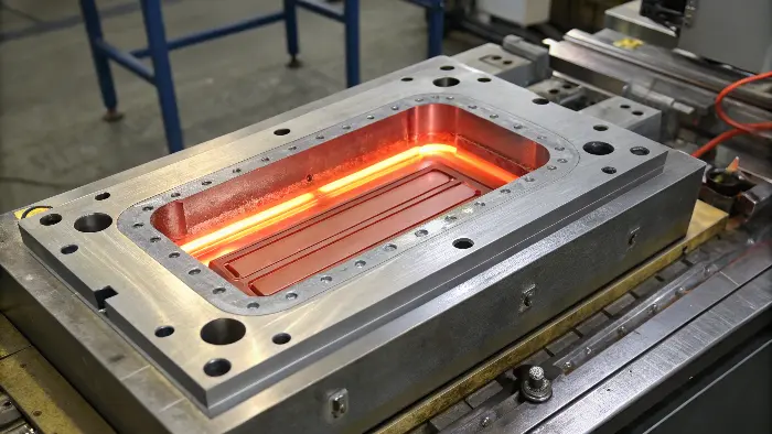
The gate is the opening where molten plastic enters the mold cavity. Its position and type are super important.
- Avoid Direct Impingement: The golden rule! You don’t want the high-velocity stream of hot plastic hitting your insert head-on. This can push the insert out of position, bend it (if it’s delicate), or cause uneven cooling and stress.
- Gate Types:
- Tab Gate: Often a good choice as it directs flow along a wall rather than at an insert.
- Submarine (Sub) Gate or Tunnel Gate: Can be useful for automatic de-gating, but placement needs to be careful to avoid jetting towards an insert.
- Film Gate or Fan Gate: Spreads the flow out, which can be good for filling around larger inserts or flat areas, reducing localized pressure.
- Multiple Gates: For larger parts or parts with complex insert geometry, using multiple gates can help the plastic flow more evenly and fill the cavity completely without excessive pressure on any single point of the insert.
- Runner System: The channels that lead the plastic to the gates should be "balanced." This means they are designed so that all cavities (if it’s a multi-cavity mold) or all parts of a single large cavity fill at the same time and pressure. This prevents one area from being overpacked while another is underfilled.
I often use mold flow analysis software with my clients. It simulates how the plastic will flow into the mold and around the inserts. This helps us visualize potential problems like "jetting" (where the plastic shoots across the cavity) or "weld lines" (where two flow fronts meet) and adjust the gate and runner design before any steel is cut for the mold. It’s a fantastic tool for optimizing the design. For example, we might see that a single gate is causing the insert to shift slightly. By adding a second gate or changing to a film gate, we can balance the flow and keep the insert stable.
Gate Types and Their Suitability for Insert Molding
| Gate Type | Advantage for Insert Molding | Potential Concern |
|---|---|---|
| Tab Gate | Directs flow along a wall, good for avoiding direct impact on insert. Easy to remove. | Can leave a larger vestige. |
| Submarine Gate | Allows automatic de-gating. Can be hidden. | Requires careful placement to avoid jetting at insert. |
| Film/Fan Gate | Spreads flow over a wide area, good for even filling around large inserts, reduces stress. | Can be more complex to design and machine. |
| Cashew Gate | Allows gating onto an internal surface, good for aesthetics. | Similar concerns to submarine gates regarding jetting. |
How Can You Design for Secure Insert Retention and Prevent Movement During Molding?
Your insert looks great, but if it moves during the high-pressure injection process, your part is ruined. Insert shifting leads to misaligned components, inconsistent part quality, and potentially damaged molds, causing significant production delays and costs. We need to explore design strategies for both the mold and the insert itself to ensure it stays exactly where it’s supposed to be.
Designing for secure insert retention involves creating features in the mold cavity that precisely locate and hold the insert, and features on the insert itself that resist the forces of flowing plastic. This can include support pins, custom-fit pockets in the mold, and designing the insert with shoulders or asymmetrical shapes that prevent rotation or displacement during the injection phase.
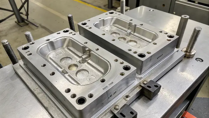
Keeping that insert locked in place is a top priority. Here’s how we tackle it:
- Mold Features for Location and Support:
- Support Pins: These are pins in the mold that the insert rests on or against. They need to be robust enough not to bend under injection pressure.
- Custom Pockets/Nests: The mold cavity can be shaped to create a precise pocket where the insert fits snugly. This is very effective for complex insert shapes.
- Crush Ribs: These are small, raised features in the mold that slightly deform or "crush" against the insert when the mold closes, holding it tightly. Use with caution as they can stress the insert if not designed properly.
- Magnetic Holders: If your inserts are made of a ferrous (iron-containing) metal, magnets can be embedded in the mold to help hold them in place.
- Insert Features for Anti-Rotation and Stability:
- Shoulders or Flanges: As mentioned before, these can rest against a surface in the mold, preventing the insert from being pushed too far.
- Asymmetrical Shapes/Flats/Keyways: If an insert is perfectly round, it can rotate. Adding a flat side or a keyway that mates with a feature in the mold prevents this.
- Bosses or Protrusions: Features on the insert that fit into corresponding recesses in the mold can provide very positive location.
- Balancing Support with Aesthetics:
- Be mindful that any feature in the mold that touches the insert might leave a small witness mark on the final part. This needs to be considered, especially for cosmetic surfaces.
- Understanding Plastic Flow Forces:
- The incoming molten plastic exerts significant force. You need to anticipate the direction and magnitude of this force and design your retention features to counteract it. Again, mold flow analysis can be helpful here.
I worked on a part with a long, thin metal rod as an insert. Initially, it was only supported at the ends. The force of the plastic flowing past the middle of the rod was causing it to bow. We had to add a small, retractable support pin in the middle of the mold that engaged the rod during injection and then pulled back just before ejection. It was a bit more complex, but it solved the problem perfectly.
Applications of Insert Molding and Overmolding
Insert Molding Applications:
Automotive: Produces long-lasting parts such as knobs, handles, and connectors with metal inserts for strength and plastic for appearance or insulation.
Medical Devices: Produces precise components like surgical instruments or device enclosures, with metal for durability and plastic for comfortable grips.
Electronics: Seals connectors, sensors, or circuit components, insulates and provides structural reinforcement.
Consumer Products: Employed in appliances, tools, and toys, to embed metal components for strength into plastic housing.
Aerospace: Manufactures light yet stiff components like fittings or brackets with metal inserts to enhance mechanical performance.
Overmolding Applications:
Tool Handles: Features soft, ergonomic grips (e.g., rubber over plastic or metal) to provide comfort and to avoid slipping.
Medical Devices: Creates non-slip, ergonomic grips for surgical instruments or devices, usually made of biocompatible materials.
Consumer Electronics: Includes device housings with soft-touch coatings or protective finishes, like remote controls or cell phone cases.
Sporting Goods: Produces club or racket grips, with hard cores and cushioned surfaces.
Automotive: Used in interior components like steering wheels or gear knobs, where hard bases are combined with soft touch coatings.
Key Difference:
Insert molding inserts other materials or metal into plastic, with an emphasis on structural integration. Overmolding covers one material (usually rubber or soft plastic) on top of another (metal or plastic) for enhanced ergonomics, appearance, or protection.
Methods for Insert Retention in the Mold
| Retention Method | How It Works | Key Consideration |
|---|---|---|
| Support Pins | Pins in the mold provide physical support against plastic flow forces. | Can leave witness marks; must be robust. |
| Custom Pockets/Nests | Mold cavity is shaped to closely match and hold the insert. | Requires precise machining of mold and insert. |
| Crush Ribs | Small mold features that deform slightly to grip the insert. | Must be carefully designed to avoid over-stressing insert. |
| Magnetic Holders | Magnets in the mold hold ferrous inserts in place. | Only for magnetic insert materials. |
| Insert Features | Shoulders, flats, keys on the insert mate with mold features for positive location. | Requires these features to be designed into the insert. |
Conclusion
Successful insert molding is a blend of art and science, with careful design being the foundation. By thoughtfully considering the insert design itself, material choices, gate and runner strategies, and methods for secure insert retention, you can avoid many common pitfalls. I hope this guide from CKMOLD gives you the confidence to tackle your next insert molding project with success, creating robust and reliable products.
FAQs
What is two-shot injection molding?
Two-shot molding is another term for overmolding. Also referred to as dual-shot, multi-shot, or double-shot molding, it simply refers to molding an overmold plastic part onto a second plastic part (substrate) in one operation. It is done in one operation and allows engineers to manufacture multi-material or multi-colored parts without assembly.
What Plastics Can You Overmold
Some of the plastics that can be overmolded are:
- High-density polyethylene (HDPE)
- PEEK resin
- Polymethyl methacrylate acrylic (PMMA) Acrylonitrile butadiene styrene (ABS) PBTR resin
What are inserts in injection molding?
Inserts are not plastic parts which play a crucial role in insert molding. They are filled into the mold and plastic is injected into them. They are typically simple items, e.g., rod or thread. They may, however, be complex, e.g., a battery.
What is TPE Overmolding?
This is a process that entails coming together and laying down TPE (thermoplastic elastomer) on a pre-existing substrate or plastic component. This helps a chemical bond between the plastic component and the TPE to be formed.
Is Insert Molding Different from 2K Injection Molding?
Whereas insert molding involves molding a secondary part onto a substrate, 2K injection molding is entirely different. Double injection (2-shot molding) is a highly specialized manufacturing process employed in the manufacturing of intricate injection-molded products. It is an entirely automatic process that involves multi-material injection into single, multi-chamber molds.
