
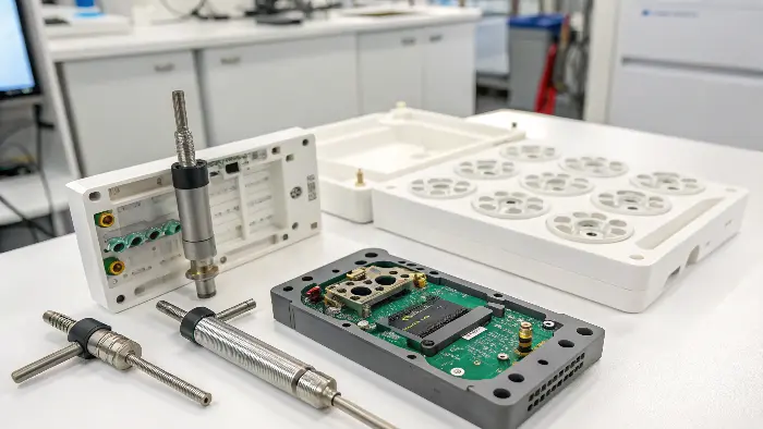
Quick answer: A reliable insert-molding process controls the insert before, during and after plastic flow. Define insert tolerances and orientation, locate it on functional datums, retain it against gravity and melt loading, seal against unwanted flash, verify presence and position, and validate bond or mechanical capture using end-use tests. Loading speed matters only after the retention mechanism and failure reactions are engineered.
Release Decision Matrix
| Failure mode | Design/process evidence | Detection or prevention |
|---|---|---|
| Missing or reversed insert | Orientation features, work instruction and sensor logic | Poka-yoke, presence check and reject lockout |
| Insert movement | Retention features, flow direction and pressure/load review | Trial measurement, witness inspection and cavity trace |
| Flash on insert | Shutoff geometry, insert tolerance and support | Controlled fit inspection and visual criteria |
| Weak interface | Material compatibility, cleanliness, capture geometry and test plan | Pull, torque, leak or functional test as required |
Approval Checklist
- Release insert material, finish, datums, tolerances and cleanliness.
- Inspect the features that locate, seal and carry product load.
- Complete tolerance analysis across insert, nest and molded CTQs.
- Review insert motion under closing, gravity and plastic-flow loads.
- Validate shutoff contact, wear and flash acceptance.
- Challenge presence, orientation, seating and reaction controls.
- Test actual pull, torque, leak, electrical or assembly function.
- Define revalidation triggers for insert and process changes.
Define the Insert as a Controlled Component
Release an insert drawing with material, coating or plating, dimensional tolerances, edge condition, cleanliness, orientation, storage and lot identification. Clarify whether the insert supplier’s process can change surface energy, hardness, burr or geometry that affects molding.
Establish incoming checks around the features that locate, seal and carry load. A thread or electrical feature can pass its own specification while the insert’s molding datum or flatness prevents reliable seating.
Locate on Functional Datums
Use stable insert features to establish position without over-constraining normal tolerance variation. Identify which mold surface controls axial, radial and rotational location and where compliance is permitted. Avoid relying on an inconsistent cosmetic edge as the primary datum.
Perform tolerance analysis across insert, nest, shutoff and molded feature. Include thermal effects when insert preheat or a large material mismatch can shift seating or final dimensions.
Retain Against Loading and Plastic Pressure
Model the insert’s tendency to lift, rotate, slide or vibrate during mold closing and filling. Review flow direction and the area exposed to cavity pressure. Retention may use pins, magnets, clips, vacuum, threaded location or geometric capture, selected for material, temperature and cleanliness.
Retention must release the finished part without damaging it. Protect thin inserts from bending and avoid a clamp force that changes the controlled dimension. Validate retention after normal wear and contamination, not only with a new nest.
Control Shutoff, Sealing and Thermal Condition
Define controlled contact where plastic must not pass. Review insert tolerance, mold deflection, wear, burr and coating buildup against the shutoff. Provide replaceable wear elements where repeated loading can erode sealing surfaces.
Use preheat only for a stated objective such as interface behavior, flow, moisture or thermal shock, and record the actual insert condition at loading. A nominal heater setting does not prove the insert reached a repeatable temperature.
Engineer Loading, Sensing and Reaction
Set manual or automated handling rules that prevent wrong orientation, contamination and damage. Verify insert identity, count, position and seating with sensing appropriate to risk. Challenge the sensor with missing, doubled, tilted and wrong inserts during validation.
Define the machine reaction to a failed check and prevent the next cycle until disposition is clear. Trace insert lot, cavity and molded lot where product risk requires it. Human visual confirmation alone may be insufficient for hidden or high-consequence inserts.
Validate the Interface and Production Window
Measure insert position and molded CTQs across cavities and process-window challenges. Inspect flash, resin coverage, cracking, voids, contamination and ejection. Use destructive sectioning during development where it reveals hidden encapsulation or movement.
Test the mechanism the product needs: pull-out, torque, electrical continuity, leak, sealing, fatigue, thermal cycling or assembly. State sample conditioning and failure definition. Revalidate after insert supplier, coating, nest, resin, preheat or loading-system changes.
Illustrative Threaded-Insert Movement Study
Illustrative engineering example—not a claimed CKMOLD customer result: A threaded insert meets incoming dimensions but tilts only in cavities reached first by the flow front. Partial-fill samples show directional loading before surrounding plastic provides support. The team changes retention contact and verifies position through a controlled fill sequence, torque testing and repeated automated loading challenges.
Supporting Review Resources
- insert molding and overmolding
- DFM analysis
- mold testing and validation
- production injection molding
Questions Before Approval
What is the main insert-molding risk?
There is no single main risk; location, movement, flash, contamination, weak capture and missing inserts must be ranked by product consequence.
Are magnets generally suitable for insert retention?
No. Insert material, temperature, cleanliness, available force, orientation, demolding and sensing must support their use.
How should insert bonding be validated?
Use the end-use mechanism—such as pull, torque, leak, fatigue or electrical performance—with defined conditioning and failure criteria.
When should insert molding be revalidated?
Revalidate affected risks after changes to insert source or finish, nest, mold, resin, preheat, loading, sensing or process window.
Apply the Insert Retention and Loading Validation for Insert Molding review to your released design. Share the function, exact resin, annual volume, CTQs, cosmetic limits and launch timing through the CKMOLD project form. If CAD is relevant, send it directly to jerry@ckmold.com; the form does not require an upload.