The mold presents a finished piece of plastic that has defects, which cost you both in time and savings. You end up with reject pile and you are unsure of whether it is the material, the machine itself or the mold that is the problem. Every non-functional component is a waste of money and time. An effective systematic evaluation process should enable you to identify the core of the problem and then you will be able to put your production back on SS.
To identify injection molding defects, start with the type of defect, e.g., flash, sink marks, or short shots. Then, step by step, examine the four main areas: the plastic material, the injection mold, the molding machine, and the process parameters. This "4M" approach (Material, Mold, Machine, Method) allows you to regulate variables and try changes in a logical manner. Documenting each change and result is necessary to reach a repeatable solution and avert repeat defects.
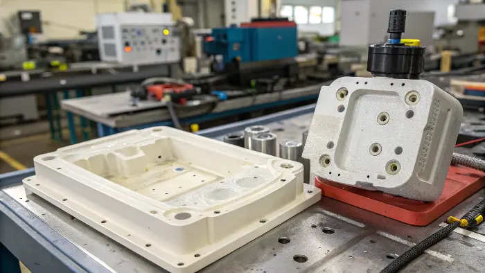
It can be like playing a detective to identify precisely the cause of a molding problem. It needs an acute observation and a clear strategy. However, before one can find a solution to a problem, one has to understand what he/she is seeking. Let us see what the typical perpetrators you will find back on the factory floor. Learning such defects will get you started in understanding the molding process and how you can make all the parts meet your standards.
What are the most common defects in injection molding?
You have made an ideal component on your screen and the actual samples show all manner of flaws, in warping, burn mark incursion etc. These flaws may adversely affect the performance, aesthetic values and stability of the part and cause rejection by a client and high rework costs. There is a rush to have it fixed. Through the mastering of the most popular defects in molding, one is able to correct the problem at hand by a diagnosis within a short time frame and begin working on resolving it.
Sink marks, flash, vacuum voids, warping, flow lines, short shots, weld lines, and surface delamination are common injection molding defects. Each of them has a characteristic look and suggests something about a problem in the molding process. Short shots, for instance, suggest that mold filling is incomplete, while flash indicates that too much material is flowing out of the mold cavity. Identification of these visual indicators is the start of successful troubleshooting and quality control on the line.
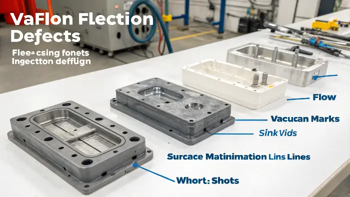
To see a defect is a battle half way. I recall such happens on one large project when we could not stop stubborn sink marks in a thick-wall part of a consumer product. These depression points were not acceptable to the client who was concerned about the looks. This labeled defect as a sink mark which indicates we first should be looking into cooling time, holding pressure and volume of the material. It was not a physical problem, but a process problem. This diagnosis at the onset spared us the effort of looking at false delusions.
Let’s break down some of these common troublemakers.
Visual and Structural Defects
Understanding the difference between a surface-level issue and a structural one is key. Some defects are just ugly, while others can cause the part to fail under stress.
Here is a quick guide to some of the defects I see most often:
| Defect Name | Description | Common Causes |
|---|---|---|
| Flash | A thin layer of excess plastic that escapes the mold cavity at the parting line. | Clamping force too low, injection pressure too high, worn-out mold. |
| Sink Marks | Small craters or depressions on the surface of the part, usually over thick sections. | Holding pressure too low, cooling time too short, thick wall sections. |
| Short Shot | The mold cavity is not completely filled, resulting in an incomplete part. | Injection speed or pressure too low, blocked gates, insufficient material. |
| Warping | The part distorts or bends as it cools due to uneven shrinkage. | Uneven cooling, inconsistent wall thickness, material stress. |
| Weld Lines | A visible line where two or more plastic flow fronts meet and fail to fuse properly. | Low melt temperature, slow injection speed, poor gate location. |
| Burn Marks | Black or brown scorch marks on the part, often at the end of the flow path. | Trapped air overheating, injection speed too high, inadequate venting. |
Knowing this table is like having a diagnostic checklist. When you see a flaw, you can immediately narrow down the potential causes and start your investigation in the right place.
What are the critical parameters of injection molding?
You are trying to correct a defect in a molding, and you are changing random settings on the machine which is not producing results. You are wearing out material, machine-time and energy without approaching any solution. Your production manager is losing his/her patience and you are feeling the heat. Identifying the few, really critical process parameters will enable you to use the adjustments that can make the most significant contribution to the part quality.
The five most significant injection molding parameters are injection speed, injection pressure, mold temperature, melt temperature, and holding pressure (or packing pressure). These parameters exert the greatest influence on how the plastic flows, cools, and solidifies in the mold. Accurate control and balance of these parameters are essential to produce consistent, high-quality parts as well as successfully troubleshoot any defect that occurs during production.
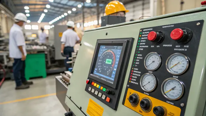
Regard these parameters as the five biggest levers that you can actuate in order to have some control over the quality of your part. When I was young in my profession, I did not care so much about mold temperature. We had irregular results on a part of ABS housing. The segments were glossy on set of areas and matt on other areas. As it would happen the cooling channels were failing to keep the temperature constant over the entire face of the mold. We moved the water flow and put the mold temperature at a constant and the issue disappeared. Easy to correct, but a massive lesson of how all these parameters are tied together.
Temperature, Pressure, and Speed
Let’s look at how these core parameters interact and what they control. Getting the balance right is the art of molding.
Temperature Control (Melt and Mold)
The action of melt temperature influences the viscosity of the plastic. When it is too hot, the material may get degraded. Too cold, it will not even flow out instinctively, this may result in short tabs or weld lines. Temperature of molds is equally important. It regulates the chill on the plastic. A warmer mold helps the plastic fill out more and will give fewer sink marks but may cost more in cycle time. The cycle is increased by use of a cooler mold which may result in warping or floured finish.
Pressure Management (Injection and Holding)
Injection pressure is the pressure which forces the molten plastic to fill in the mold cavity. It must be sufficient to saturate the part without any problems and in a short time. After filling the cavity about 75 percent, the filling is changed to pressure maintenance. This further reduced pressure holds more material in the cavity to cover up shrinkage of the part as it cools off. The secret to avoiding sink marks and the occurrence of voids is to obtain the correct holding pressure.
Speed and Time
Injection speed, is how fast the plastic is injected into the mold. A faster speed can increase the amount of material available to fill thin areas so that you have a stronger weld line, but it can also produce burn marks if the air gets trapped. Cooling time is the time the part spends in the mold after mold filling. It must be long to allow the material to solidify in so it can be popped out without slumping.
Here’s a simple table showing how adjusting a parameter can affect common defects:
| Parameter Adjustment | Effect on Sink Marks | Effect on Flash |
|---|---|---|
| Increase Holding Pressure | Decreases | Increases |
| Increase Cooling Time | Decreases | No significant effect |
| Decrease Melt Temperature | Decreases | Decreases |
| Increase Injection Speed | Can Increase | Increases |
Understanding these relationships helps you make intelligent, targeted changes instead of just guessing.
What are the fundamental constraints of injection molding?
Your CAD design of the product is awesome, yet the manufacturer claims it will never mold its way. This is because, it will subject you to timewasting and frustrating redesigns and this may lead to a delayed project launch as well as the distortion of your original design concept. You feel constrained with the process. By being aware of the limitations of injection molding right at the beginning, you will be able to create parts which are not just functional, but also manufacturable.
The most important injection molding constraints are part design, material characteristics, and mold complexity. Major design constraints are uniform wall thickness, i.e., draft angles for ejection, and elimination of undercuts hindering mold action. Material constraints are processing temperatures and shrink rates. Finally, the high initial cost and long lead time for mold manufacturing are major project-level constraints that have to be overcome.
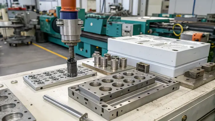
On every project I say to the designers, ”Think like the plastic”. Just imagine how it will fill up the cavity, how it will cool and how the part will release out of the mold. Such a change in attitude is what makes breaking most of the design constraints a reality rather than a costly issue on the factory floor. When a part is manufacturability (DFM) oriented at the very beginning, the resulting project will be always smoother, faster, and cheaper.
Design, Material, and Tooling Constraints
These three areas are where the rules of the road are written for injection molding. Ignoring them leads to trouble.
Design Constraints (DFM)
This is the most important area for a product designer to master.
- Thickness of the wall: This is the golden rule. Walls should be as uniform in thickness as possible. Thick parts cool more slowly than thin parts, leading to differential shrinkage, which leads to warping and sink marks.
- Draft Angles: All components need a minor taper on their vertical edges, referred to as a draft angle. 1-2 degrees will normally be enough. This allows the part to be easily pushed out of the mold. Without it, you will get drag marks or the part will stick.
- Radii and Corners: Thin interior corners create stress concentrations in the part and are difficult to fill. Putting a small radius (fillet) on all of the corners makes the part stronger and enables the plastic to flow more easily.
- Undercuts: Undercuts are side holes or clips that stop the part from being pushed straight out of the mold. They may be made but are hard and expensive to achieve with intricate mold mechanisms like side-actions or lifters.
Material and Tooling Constraints
The limitation also lies in the material you use, as well as on whatever tool you make. The reaction of different plastics to shrinking is different. To cite an example, Polypropylene (PP) can shrink twice as much than Acrylonitrile Butadiene Styrene (ABS). This contraction has to be considered in designing the mold. A big limitation is the mold itself. A non-complex, just open and shut mold is fairly inexpensive and quickly produced. A complex mold- multiple side-actions to form undercuts will cost far much more and will also take very long time to build. It is a trade off between the cost of tooling and the complexity of the parts and there is always an element of trade off in any project.
What do innovations and technologies in the reduction of injection Molding faults mean?
The injection molding technology is constantly changing and it is the innovation and technological progress that can make a significant contribution to the reduction of defects and improvement of the products.
Such innovations in technology have transformed how manufacturers have focused on the injection molding process to provide highly accurate control, quality assurance, and reduction of wastes.
Mold Making:
Mold design incorporates the technology of using 3D printing to make molds quickly, to perform prototyping and testing. The innovation aids in determining any possible pounds challenges that may occur during mass manufacturing, and the possibility of defective produces is decreased.
Simulation Software:
Sophisticated simulation software allows one to visualize (virtually) the molding process, warping, cooling and flow. Such predictive analysis assists in the necessary adjustment to prevent occurrence of sink marks and air traps which are such common defects.
Automated Quality Control Systems:
Automated quality control systems with applications in quality control such as vision systems and defect detection using AI have greatly enhanced the range of capability to diagnose and correct defects early in the production process.
Precision Temperature Control Systems:
These systems give more precision to the control of the mold and melt temperature that is vital in curbing resistance stresses, warping, sink marks, and residual temperatures in the molded-product.
So, how do you systematically solve injection molding problems?
You have discerned that you have a defect and you already know the parameters but you simply require a dependable way of locating the solution without any speculations. Trial-and-error is messy and so it worsens the situation. A systematic approach is what you require so that you do not end up spinning your wheels. When using a systematized trouble shooting technique such as the 4M technique, a clear pathway is obtained to diagnose any injection molding problem and subsequently solve it effortlessly.
To correct injection molding defects, use the "4M" rule: Material, Mold, Machine, and Method (Process). First, verify that the material is proper and dry. Second, verify that the mold is free of defects like clogged vents or cooling channels. Third, verify the machine setup and operation. Fourth, stepwise change one process parameter at a time beginning with the one most likely to produce the specific defect. Document each change and outcome to properly isolate the root cause.
I’ve known teams make three changes simultaneously. The issue may resolve itself, but they have no idea which change did the trick. That’s not a solution; that’s accident. And accident wears off. A disciplined process assures you that when you do find a solution, you know why it works. That separates amateurs from professionals. That lets you create a stable, reproducible process and avoid having the problem occur again and again.
A Step-by-Step Troubleshooting Guide
Here is the simple, logical process I use on the factory floor.
Step 1: Identify and Document the Problem
First, be specific. Don’t just say "the part is bad." Is it a short shot? Is there flash on the left side? Are there sink marks over the ribs? Take a picture. Note where on the part the defect occurs and how often. This detailed observation is your starting point.
Step 2: The 4M Checklist
Get through the four potential trouble spots in a step-by-step order. Don’t race out and alter process settings on the machine.
- Material: Is it the right grade of plastic? Most importantly, is it dry? Certain plastics absorb moisture from the air, which evaporates upon molding and causes severe flaws. Inspect for dryer time and temperature.
- Mold: Is the mold clean of contamination? Are vents clogged? Are all cooling channels clear of obstructions? Is there any core or cavity damage?
- Machine: Is the machine running consistently? Monitor the nozzle temperature, screw recovery, and clamp tonnage. Is the machine capable of providing the required pressure and shot size?
Step 3: Adjust the Method (Process) and Document
If material, mold, and machine are all in good shape, then let’s look at the process parameters. You only change one variable at a time. If you do have flash, for example, you would first decrease the injection pressure a little bit. Make the change, run a few parts, and observe what happens. Document it. If it failed, put the parameter back to where you started and make the next reasonable change, like turning up the clamp force.
Here’s a quick example:
| Defect | Possible Cause (4M) | Corrective Action (in order) |
|---|---|---|
| Short Shot | Method: Process settings are off. | 1. Increase injection pressure. 2. Increase injection speed. 3. Increase melt temperature. |
| Mold: Gate is blocked. | 1. Inspect and clean the gate. | |
| Material: Material is too stiff. | 1. Check melt temperature against material spec sheet. |
This methodical process takes the panic out of troubleshooting and turns it into a simple, logical puzzle.
Conclusion
Injection molding problem evaluations are skills that are developed based on a system. Acceptable areas of guesswork can be eliminated by way of knowing the usual defects, crucial parameters, or restraint with it comes to the process. Applying a systematic approach such as the 4M analysis enables you to solve problems with the confidence and ability to generate resolutions that can be repeated. This makes the troubles into blessings that would help you to perfect your work process and touch the skill of molding.
