You modeled a flawless looking part in your CAD tool and when you receive the first sets of production the parts returned are deformed, they have unsightly sink marks and other flaws. It is a frustrating procedure that distorts the aspect and merit of the part, creating re-designing of tools and schedule-blowing projects. The common cause is usually an asymmetrical thickness of the walls and the ability to apply this single design principle can get rid of a super-majority of many of the most frequently occurring issues with moldings.
Thickness of the walls of a part greatly influences manufacturing process and performance of a part that is made of plastic. The uniform thickness of a wall will play an important role in approaching to the uniform filling of the mold, uniform cooling of the part, and controlling internal stresses. Non-uniform thickness is among the main reasons that lead to major defects, which are warpage, sink mark, void, and short shots. Setting the wall thickness is the key to creating a high-quality, functional and a beautiful plastic part.
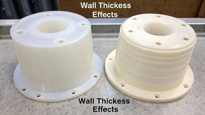
Now that you understand the general principle, you’re probably wondering why it matters so much. What if you get it wrong, and how, exactly? How would you know the right thickness for your specific material and application? The devil’s in the details, and understanding those details is what will make you a good designer. Let’s dive into the nitty-gritty that will save you time, money, and a whole lot of headaches.
Does wall thickness need to be taken into consideration?
By being in a hurry to make a design, quickly, one might tend to look at all the features as well as the outside shape of the design, with wall thickness as a second thought. I have watched it occur in so many cases. However, this is a cardinal rule that should not be ignored. The commonest cause that I can discern in failure of parts during the initial molding trial, giving the whole team a headache, is the lack of it. Wall thickness should be put into consideration even at the initial sketch.
Actually, of course, wall thickness does come into play. It is one of the most important of the major considerations of injection moulding design. It directly influences the material flow, cooling time, mechanical strength and even general appearance of the component. Ignoring this consideration of wall thickness will certainly cause faults in the manufacturing of products, drive up costs and delay the market launch. It is a responsibility of good part design which cannot be dispensed with.
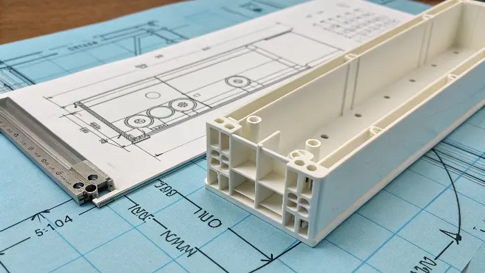
I learned this lesson the hard way early in my career. I designed a housing that had several thick, solid bosses for screws. On paper, it looked strong. But the final parts looked terrible, with a big, ugly sink mark over every single boss. We had to stop production and pay for expensive tool modifications to core out the bosses and add ribs. I never made that mistake again. From that day on, wall thickness became the first thing I check on any design.
What is the Significance of wall thickness in product design?
Plastic Product wall thickness is an important structural aspect that is widely talked about and addressed in plastic product structure design. It is the thickness value between the external and internal walls of a plastic component. Wall thickness is the fundamental parameter that dictates the overall product thickness and is usually prescribed in the structural design procedure.
It is important to understand the importance of wall thickness properties in the structural design of plastic products at the time of mold design and during the process of injection molding, since it is a significant factor in the manufacture of plastic products through the commonly employed injection molding process.
In product design, the importance of wall thickness is approximately to minimize material consumption while enhancing part quality and manufacturing speed. Ideal wall thickness can minimize the quantity of plastic used and the weight of the molded component—in most instances, thicker walls can be substituted with thinner walls.
Injection molded parts that are poorly designed with wall thickness issues can cause defects such as sinkholes, warping, and short shots. These issues raise rejection rates and, by extension, your overall cost of parts. It is longer to cool thicker walls compared to thinner walls, yet good cooling is essential for injection molding success.
Therefore, wall thickness influences rates of cooling and, as a result, injection molding cycle times.
Why It’s a Non-Negotiable Rule
Thinking about wall thickness comes down to three key pillars of the injection molding process: filling, cooling, and shrinkage.
-
Filling: Melted plastic behaves like a river and will always take the path of least resistance. It’s not necessarily a bad thing if the plastic must flow from thin to thick. But if it must flow from thick to much thinner, pressure drops considerably and the plastic can cool and harden before it fills the thin space all the way. This produces an incomplete part, which is called a "short shot."
-
Cooling: This is the major one. Thicker plastic parts take a long time to cool and harden compared to thinner parts. The rate of cooling is the main reason for warpage and internal stress. The thick part is still cooling and contracting while the thin part is already hardened and stiff. This results in a tug-of-war that pulls and distorts the part out of shape.
-
Shrinkage: All plastics shrink as they cool. A thicker section will shrink more than a thinner one. As the center of a thick section cools, it draws material towards it. This can lead to unattractive surface depressions known as "sink marks" or, in very thick sections, create internal vacuum bubbles known as "voids."
| Process Stage | Impact of Non-Uniform Wall Thickness |
|---|---|
| Filling | Can cause short shots, weld lines, and burn marks. |
| Cooling | Creates differential cooling rates, leading to internal stress and warpage. |
| Shrinkage | Causes cosmetic defects like sink marks and structural defects like voids. |
What is the problem with inconsistent wall thickness?
You understand that even wall thickness is critical, but what precisely happens when you have a heavy section adjacent to a light one? These defects are not cosmetic. They can result in catastrophic part failure, destroy how your parts fit together, and make your finished product appear cheap and low quality. By knowing precisely what defects exist, you’re in the position to identify them in your CAD model and design them out of existence prior to any steel being machined.
The major problem with uneven wall thickness is differential shrinkage. The thicker sections take a very long time to solidify and shrink relative to the thinner sections. This results in a tug-of-war in the part during solidification, causing high internal stress, warpage (twisting), and cosmetic flaws like sink marks and voids. It also makes filling difficult, which can lead to short shots (incomplete parts) or burn marks from trapped air. It makes the manufacturing process unpredictable and unreliable.
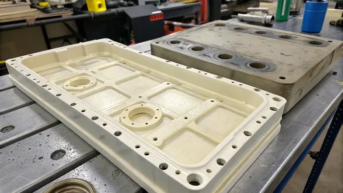
Think of it like this: you’re trying to build a wall with big, wet mud bricks and small, dry clay bricks. As the mud bricks dry and shrink, they will pull on the stable clay bricks, cracking the mortar and making the whole wall crooked. The same thing happens inside your plastic part on a microscopic level, and the results are just as damaging.
A List of Common Defects
Let’s look at the most common criminals caused by poor wall thickness management.
Warpage: The Silent Twister
This is the most frequent outcome of non-uniform walls. When the part hardens in the mold, the thin sections harden first. The thick sections, remaining hot and pliable, keep cooling and contracting. This contracting tugs on the already-stiff thin sections, and the whole part distorts, twists, or bows. When the part is pushed out, it relieves these internal stresses by warping out of shape.
Sink Marks and Voids: Surface Killers
They are two aspects of one and the same thing. They happen when a thick section, such as a boss or rib, is poorly designed. When the thick section sets, the inside will contract and draw material to itself.
- Sink Mark: When the part surface skin is in a softened state, it gets drawn into the part and creates a depression on the part surface that is visible. * Void: While the surface skin will harden and be strong, the shrink material will deteriorate from the inside and form a vacuum bubble or "void" in the part. It is a fault that will significantly compromise the part.
Flow Problems: Short Shots and Weld Lines
Abrupt changes in thickness disrupt the flow of molten plastic. When plastic flows from a thick runner into a thin cavity wall, it has to speed up and squeeze through a smaller space. This can increase shear stress on the material, and if the wall is too thin for the flow length, the plastic can freeze before the part is full, causing a short shot.
| Defect | Primary Cause (related to wall thickness) | Design Solution |
|---|---|---|
| Warpage | Differential cooling and shrinkage between thick and thin sections. | Maintain uniform wall thickness. |
| Sink Marks | A thick section (rib, boss) shrinking and pulling the surface inward. | Core out thick sections; use the 60% rule for ribs. |
| Voids | Internal shrinkage in a very thick section with a rigid surface. | Eliminate thick sections entirely. |
| Short Shots | Plastic freezing in a thin section before the mold is full. | Increase wall thickness or add flow channels. |
How thick should mold walls be?
Good, you’re with me. Uniform walls are the solution. What is the "proper" thickness? 1mm? 3mm? 5mm? Too thin a thickness compromises the strength of the part and makes it hard to fill. Too thick a thickness wastes material, greatly reduces the cooling time, and reintroduces the threat of sink marks and voids. There is no one magic number. Optimal wall thickness is an artistic compromise.
There is no universal rule for mold wall thickness; it is more of a matter of plastic material, part size, and structural requirements. For the majority of common thermoplastics, a standard rule is 1.5mm to 3mm (0.060"" to 0.120""). The most important rule is to maintain thickness as uniform as possible. Any variation should be a gradual one, and heavy thicknesses must be cored out and reinforced with ribs for strength.
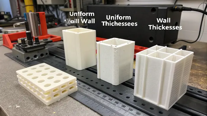
The goal is to find the thinnest possible wall that still meets all the structural and manufacturing requirements for your part. A thinner wall means less material used, a faster cooling cycle, and lower cost per part. This is where a designer’s experience really comes into play.
Finding the Sweet Spot
Here are the factors you need to balance to determine the ideal thickness.
The "Coring Out" Principle
That is the best way in terms of controlling the thickness of walls. You cannot, on making one of the parts any thing so stout that it will have strength, and make it very solid and very heavy, because then you could not have an even wall. You must "core it out," to make it have an even wall. You then insert thin ribs to give the part the strength and stiffness that is needed. This does the same strength with less material, no sink marks and the saving in cooling time is enormous.
The 60% Rule for Ribs
By ribbing, you have a thickness section where the rib is mounted on the wall. In order to prevent this from creating a sink mark on the cosmetic surface, there was once an old rule of thumb that stated that the bottom of the rib was not to be greater than 60% of the nominal wall that it is mounted on. That means, if your part wall is 2.5mm, your ribs are not to be greater than 1.5mm thickness at the bottom.
Material Selection Different plastics have different flow characteristics. A high-flow plastic like Polypropylene (PP) will have no issues filling extremely thin sections. A hard, abrasion-resistant plastic like glass-filled Polycarbonate (PC) will require a thicker wall so that it will fill the part completely without excessive pressure.
Here are some general recommendations:
| Material | Typical Wall Thickness Range (mm) | Typical Wall Thickness Range (in) |
|---|---|---|
| ABS | 1.2 – 3.5 | 0.045 – 0.140 |
| Polycarbonate (PC) | 1.5 – 4.0 | 0.060 – 0.160 |
| Polypropylene (PP) | 0.8 – 3.8 | 0.030 – 0.150 |
| PBT | 1.0 – 3.0 | 0.040 – 0.120 |
What is the minimum wall thickness for PBT?
Well, let us be exact. Your corporation manufactures a new connector in electronics and the spec should be PBT. You ought to ensure the part is as minimized in size and as thin as possible to ensure the part is able to pass the requirement of the design. But go to extreme it can turn out to the point of components not filling well, so brittle that they would break or just not pass quality check and would have to redesign in just in time at enormous cost to the company in design cost and time, not to mention the loss of various parts in the process. Particular boundaries of the material should be comprehended.
In the case of PBT (Polybutylene Terephthalate) it is common practice to recommend a minimum thickness of approximately 0.5mm to 1.0mm (0.020" to 0.040"). This however strongly depends on grade specific (unfilled vs. glass-filled) and the distance over which plastic must flow. stiff by an order of magnitude the glass-filled grades tend to require greater wall thickness with a minimum of 1.0mm. Datasheet provided by the material supplier is always to be consulted to obtain the most accurate piece of advice.
What is the Maximum Injection Molding Wall Thickness?
Maximum wall thickness for injection molding is the maximum wall thickness recommended for a given plastic type. There are a few considerations to make when defining this dimension. Generally speaking, very thick walls are undesirable since they tend to lead to part failure. Occasionally, thicker walls are required due to high part loads, thermal insulation demands, or simply to make the part feel heavier and more real.
Above the maximum limit most injection moldable plastics possess, which, when exceeded, leads to problems like underfilling, warping, and too much dimensional deviation. Still, as an exception to the rule, the max wall thickness must be restricted to 5 mm. Like minimum wall thickness, the max wall thickness is a function of the molded plastic material.
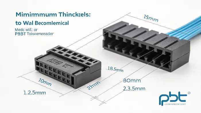
PBT is a fantastic engineering plastic, especially for electrical applications because of its high dielectric strength and resistance to solvents. But its semi-crystalline nature means it sets up (freezes) very quickly, which makes filling thin sections a challenge.
Unfilled vs. Glass-Filled PBT
There is a tremendous variation in the quality of PBT that you are employing.
- Unfilled PBT: This has a free flow to the extent of being water-like in molten form. In actually minuscule-size components with very short flow paths like smaller coil bobbins, you might get some wiggle room down to walls under 0.5mm, but you need to know what you are doing. But at least a safer bet is to begin at 0.8mm in most general uses.
- Glass-Filled PBT: Glass fiber addition (e.g., 30 percent GF-PBT) increases the strength, stiffness, and heat resistance considerably. It does, however, decrease the flow-ability of the material considerably. The fibers also impose drag and will occasionally have to be used to fill thin areas. Those, 1.0mm would be the bare minimum, and I would prefer to design to a nominal wall of 1.2mm or 1.5mm so that things will function reasonably well.
The Importance of Flow Length
The minimum thickness is not just about the material; it’s about the relationship between the thickness and how far the material has to travel from the gate. This is often called the L/T Ratio (Flow Length to Thickness). A part that is 100mm long with a 1mm wall will be much harder to fill than a part that is 20mm long with a 1mm wall. The plastic will cool and solidify before it can reach the end of the longer part. If you have a long flow path, you must increase the wall thickness to keep the material molten long enough to fill the cavity.
| PBT Grade | Minimum Recommended Wall | Key Consideration |
|---|---|---|
| Unfilled | 0.5mm – 0.8mm | Excellent flow, but lower strength. Best for small parts. |
| 15% Glass-Filled | 0.8mm – 1.0mm | Good balance of flow and stiffness. |
| 30% Glass-Filled | 1.0mm – 1.5mm | Poor flow, high stiffness. Requires thicker walls and careful gate design. |
Conclusion
The wall thickness is nothing about plastic part wrinkles. Master is consistency. It provides you with most effective defense against the manufacturing defects like Warping, sink holes or holes. An ideal thickness represents an ever-balancing motivic between properties of material, part features and the fabrication effectiveness. Given an understanding of these notions, you will be able to create superior quality cost effective molded sections which will work initially and every time.
