Engineers are in the unfortunate position of being held completely accountable for the safety and integrity of all the products and buildings that they create. Small errors in design can result in catastrophic imminent disasters (that more often than not appear in court and get litigated). From idea to implementation, four technological giants power current engineering—CAD, CAM, FEA, and CFD.
Whether designing aircraft parts, streamlining production, or modeling real-world physics, these technologies define the future of engineering. But how do they stack up? Let’s look into their purposes, distinctions, and influence!
It is because of this that products and buildings are subjected to a set of stress testing and optimization prior to deployment in the real world. But repeating the process hundreds of times (and at scale) can be extremely costly. So engineers will sometimes turn to simulation modeling tools (such as Finite Element Analysis) to mechanize and streamline this testing.
The major difference is intent: CAD (Computer-Aided Design) is for creating a part or assembly’s form—it’s the digital drafting table for establishing its form, size, and detail. FEA (Finite Element Analysis) is a simulator that’s used to predict how that form would behave when subjected to physical forces like stress, vibration, or temperature. Basically, you make what it is using CAD and simulate how it behaves using FEA before you ever build a physical model.
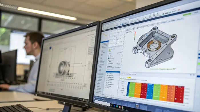
This difference is where engineering today revolves. I had to learn this lesson myself very soon into my career. My client wanted me to design a plastic clip to be assembled. It was ideal in the CAD model and the mold design was in good order. However, the initial order of components did not work in the test; they continued to break. We had to halt the manufacturing process, to adjust the costly steel mold and re-make them. Had I performed a FEA simulation I would have been able to spot the point of stress concentration within a few seconds. It was an expensive lesson, but it gave me to understand that CAD and FEA are not separate entities, but two critical components of every successful design process.
What is the difference between CAD and Ansys?
You know your CAD package, whether it’s SolidWorks, CATIA, or Inventor. Someone then mentions a simulation in "Ansys." Is Ansys a new CAD that you must familiarize yourself with? Is it a competitor? The flood of software names is confusing, and blissful ignorance of the landscape can leave you lost in technical conversation. Let’s clarify this frequent source of confusion.
The difference is category vs. brand. CAD (Computer-Aided Design) is a general category of 2D and 3D model creation programs. Ansys is a specific, market-leading brand of engineering simulation software, employed primarily for FEA runs. It’s like the difference between the word "car" and the name "Ford." One is a general concept, and the other is a specific product that does the job of that concept. You model it with a CAD program, and then you might analyze it with a program like Ansys.
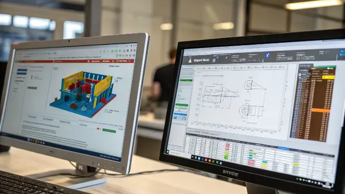
Imagine making of a house. The architectural blueprint program that you use is your CAD software. It allows you to sketch the walls, the rooms, the roof, each and every geometric particularity. Ansys, though, is more of a kind of engineering practice that you contract to study those blueprints. They use your design and carry out simulations to check how it would fare during an earthquake, how the wind can move around, and how the heat can escape through the HVAC. They do not form any drawings of the house, rather they point out to you whether or not the house you have drawn will collapse.
Function and Purpose Breakdown
While some modern CAD packages have built-in simulation tools, they are often simplified versions of what a dedicated suite like Ansys can do. Understanding their core focus is key.
| Aspect | CAD (e.g., SolidWorks, Inventor) | Ansys (Dedicated Simulation Suite) |
|---|---|---|
| Primary Goal | Create and document geometry. | Predict physical behavior and performance. |
| Core Function | Sketching, extruding, assembling parts. | Meshing, applying loads, solving physics. |
| Output | 3D models, 2D drawings, assembly files. | Stress plots, thermal maps, fluid dynamics. |
| User | Designers, drafters, mechanical engineers. | Simulation analysts, R&D engineers. |
| Complexity | Varies, but focused on geometric creation. | Very high, requires deep physics knowledge. |
The Workflow: From CAD to Ansys
The two systems complement each other in a normal working process of a professional. A designer capable of doing so such as you, Jacky, would build a detailed 3D model of a plastic part in your choice of CAD software. Once the design is to be validated, it is exported. That geometry is then imported by an analysis engineer to Ansys. The steps in Ansys follow the process of prepping the model to the means of simulation by simplifying any excessive complicated features (such as small fillers or logos that would not interfere with structural integrity), adding a mesh to the part, defining material properties, defining boundary conditions (where the part will be held) and defining loads (the action the part will receive). The computer program will then refer to intricate mathematical formulae to make a forecast. The output, a colorful map of stresses, is then returned to you the designer with suggestions such as, add a rib here or thicken this wall by 2mm.
Why FEA software is convenient?
FEA enables engineers to simulate a designed model instead of producing a physical model for test purposes.
FEA has more benefits
FEM in the course of analysis provides modeling of a wide variety of material types, and the capability to observe how restricted effects affect a limited region of design in complex geometry.
Engineers can employ software dedicated to finite element modeling to perform a large variety of tasks.
Fluid flow, deformation of a car due to impact and stress on human bones are a few examples of real-world application of finite element modeling software by engineers.
What is the primary difference between CAD and parametric building modeling?
You’re a parametric modeling specialist in product work. You’ve mastered the use of constraints, features, and parameters to generate solid models that are easy to modify. You learn of Parametric Building Modeling, or BIM, and wonder if it’s another name for the same thing. Do you need to learn it? To know where your expertise places you in the grand scheme of design, being aware of the difference is important.
The most significant distinction is the scope and the information. Both use parameters to define geometry. But parametric CAD for product design is about specifying one piece or assembly to manufacture. Parametric Building Modeling (BIM) creates a whole, information-rich model of an entire building. A BIM model not only has the form of a wall; it also contains information about the material, its thermal conductivity, its price, and how it connects to the building’s electrical and plumbing systems. It’s a building database, not a manufacturing model.
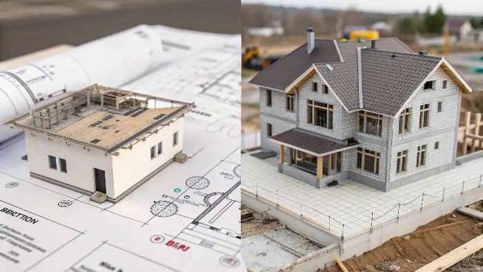
This is a classic case of different tools for different jobs. Imagine you’re designing a new doorknob. In your CAD software (like SolidWorks), you model the knob, the latch, the spindle. Your parametric model allows you to easily change the knob’s diameter or the length of the screws. Now, think about the architect designing the building where that doorknob will be installed. They use BIM software (like Revit). Their model includes the door, which is in a wall, which is on a floor. If they move that wall in the BIM model, the door moves with it, the electrical wiring diagram updates, the square footage calculation for the room changes, and the bill of materials for the drywall is automatically adjusted. It’s about managing the information of an entire construction project.
Contrasting Focus: Manufacturing vs. Construction
The end goal of each type of modeling dictates its features and the kind of data it manages.
| Feature | Parametric Mechanical CAD (for Products) | Parametric Building Modeling (BIM) |
|---|---|---|
| Primary Unit | Part / Assembly | Building / Project |
| Focus | Form, Fit, and Function for Manufacturing. | Space, Systems, and Lifecycle Management. |
| Data Included | Geometry, tolerances, material type. | Geometry, plus cost, scheduling, MEP, etc. |
| End Goal | A manufacturable object. | A constructible building and its data. |
| Key Question | "Can we make this part efficiently?" | "How does this change affect the project?" |
Why This Matters to a Product Designer
You may not ever use the BIM software directly yourself but it might be useful to learn about the principles. It brings to the fore the increased significance of data in design. Exactly the way we now apply BIM by placing lifecycle data on a wall, modern manufacturing aims at a similar vision of a "digital twin" of your CAD model connected to simulation data, tooling data, not to mention live performance data fed in by sensors on the end result.
It is no more creating a shape but a data rich product. This future can be achieved based on your parametric modeling expertise in which context, the I of BIM (Information) is being equally valued as the D of CAD (Design)!
What is the difference between FEA and the finite element method?
In technical presentations, you may encounter the terms FEA and FEM being used interchangeably. You may know what they are, but not the exact difference. Does it even exist? Applying these words correctly is a subtle but significant indication of profound technical knowledge. It differentiates the tool user from the learned person who knows the underlying principles.
There is a clear and distinct difference. The Finite Element Method (FEM) is the broad and general mathematical theory and computational approach to solving complex problems by breaking them into small, manageable pieces (finite elements). Finite Element Analysis (FEA) is the specific application of the FEM to solve a specific, real-world engineering problem, almost always with specialized computer programs.
For simplicity, FEM is the "recipe" or the "procedure," and FEA is the process of "cooking the dish" using the recipe.
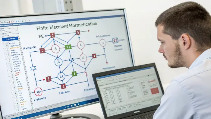
I like to think of it like learning to calculate the trajectory of a baseball. The Finite Element Method is like the laws of physics—the equations for gravity, drag, and motion. These are the fundamental principles. You could, in theory, solve them with a pencil and paper for a very simple problem. Finite Element Analysis is what happens when you use a computer program to apply those laws to a specific baseball pitch. You input the ball’s speed, spin, and the air density, and the software runs the calculations (the FEM) to give you a practical answer: the exact path the ball will take. One is the theory, the other is the application of that theory to get a result.
Types of Finite Element Method
Limitations of FEA modeling in some areas (like fluid dynamics) have necessitated a number of developments in the solution process while improving the versatility in the use of finite element analysis.
Some of the widespread types are;
The generalized finite element method
Here, shape functions are multiplied by the partition-of-unity while being defined in terms of global coordinates. This does away with re-meshing while you can create local element functions.
The extended finite method (XFEM)
Damage fracture or failure types of problems cannot be solved by the finite element method directly.
XFEM, which is based on the Galerkin method and Heaviside step functions, allows for expansion of shape functions. Each node is provided with additional degrees of freedom at the points of discontinuity to be considered.
Theory vs. Application
The distinction is crucial because it separates the underlying science from the engineering tool.
| Aspect | Finite Element Method (FEM) | Finite Element Analysis (FEA) |
|---|---|---|
| Nature | A mathematical theory, a numerical method. | An engineering application, a simulation process. |
| Form | Equations, algorithms, academic principles. | Software, workflows, practical problem-solving. |
| What it is | The "how-to" guide for solving the problem. | The act of solving the problem with the guide. |
| Example | The mathematical formula for heat transfer. | Using software to simulate heat in a CPU. |
| Who works with it | Academics, researchers, software developers. | Design engineers, analysts, product designers. |
Why the Distinction Matters
In the case of a designer such as Jacky, you will be mostly engaged in FEA. The software which you will use will be integrated into the FEM. But it is important to understand that FEM is a basis to be able to take note of the limitations of the software. An example is the type of element used (such as a tetrahedral element or a hexahedral element), a sensible FEA decision whose basis requires extensive FEM theory regarding accuracy and expense of computation. The understanding that a complex math approach is in place in the background helps to remember that FEA is not a magic make it green button. It is an immensely capable one and the quality of what you end up with comes down to the quality of what you put in and the way you know what you are doing.
Can AutoCAD do finite element analysis?
You’ve got AutoCAD experience for years. It’s a good, trusted 2D drafting and even a little bit of 3D modeling tool. Now you have a simple component and you’d like to do a quick stress analysis. What’s on everyone’s mind is, can you just do it straight from AutoCAD, or do you have to export what you’re doing and learn a whole new, complicated piece of software? It’s a perfectly reasonable question that can save you a vast amount of time and money.
The short answer is no, base AutoCAD is a design and drafting application and does not contain Finite Element Analysis (FEA) capability in its base. Its primary purpose is to properly define geometry, not to solve physical behavior. That said, Autodesk, the company that makes AutoCAD, does offer a suite of other software tools that are appropriate for this. Software like Autodesk Inventor and Fusion 360 are full parametric modelers with mature, integrated FEA capability, and they work very well with AutoCAD files.
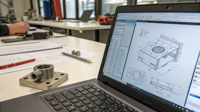
This is what I used to talk to designers. Alot of us began with Auto CAD and it is our comfort zone. It might be just the first step, however, when applied to modern product design. I recall one project where we got all the original 2d layouts as DWG files of AutoCAD. I will need to make them in 3D so that I could have the parts of a mold. As opposed to modelling them, I imported the 2D profiles into the Autodesk inventor. With that I constructed the 3D parametric models and performed stress analyses of the critical components in the integrated FEA module. When we were even cutting steel to make the mold, we had to have found and corrected three weak points. The process was fluidly connected since the products are created to complement each other.
The Right Tool for the Job in the Autodesk Ecosystem
Thinking of these programs as a toolbox is the best approach. Each tool has a specific purpose.
| Software | Primary Function | Built-in FEA Capability | Best For |
|---|---|---|---|
| AutoCAD | 2D Drafting, Basic 3D Modeling | None | Creating precise drawings and layouts. |
| Autodesk Inventor | Professional-Grade 3D Parametric Modeling | Yes (Linear Stress, Modal, Thermal) | Detailed mechanical design and analysis. |
| Autodesk Fusion 360 | Integrated CAD, CAM, CAE Platform | Yes (Extensive, cloud-based options) | Collaborative design, from concept to manufacturing. |
Software Limitations and Compatibility
This reminds me of my understanding of software limitations. AutoCAD is great at what it does: generating the definitive lines and curves of a design. But FEA demands a different type of data structure. It demands a "solid body" that can be rendered into a mesh of thousands of tiny elements. My understanding was that FEA tools tend to need to reduce complicated shapes from CAD. This is true, but the more fundamental understanding is that the software engine itself has to be designed for analysis. AutoCAD’s engine is for drafting. Inventor’s and Fusion 360’s engines are designed for parametric modeling and simulation. The good news is that since they’re all produced by Autodesk, exporting a design from AutoCAD to Inventor to perform an analysis is an easy and predictable process. You don’t have to give up your AutoCAD skills; you just have to add the correct analysis tool to your process.
Conclusion
Finally the CAD and FEA are two faces of the coin in the present day product design. CAD is the artistic instrument that shapes your ideas and FEA is the assessment application that lends you the reassurance of that shape. It is no longer a choice whether one has to understand about their various roles, the software involved and the principles involved therein. It is important in coming up with new, reliable and affordable products. Being good at them is the process of perfecting your job.
