Are your most creative packaging ideas getting stuck at the manufacturing stage? It’s frustrating when a brilliant cap design is labeled "impossible to produce," forcing you back to generic, uninspired options. The secret isn’t to limit your creativity. It’s to understand the language of mold making. By learning how to design for the mold, you can create innovative caps that are both beautiful and manufacturable, turning your vision into a reality.
Being creative with plastic cap molds of packaging relates to an ability to absorb new ideas in design and blend them with the applicable principles of injection molding. The trick here is to use Design for Manufacturing (DFM) at the onset. This entails making the right decision concerning the type of plastic used in the appearance and purpose and designing to get the wall consistency, as well as including drafting angles. In case of complicated designs, such as threads or undercuts, you have to incorporate high-tech mechanisms of the mold, such as unscrewing systems, sliders or lifters. The proactive method can show you that your creative designs are manufactured without error and efficiently.
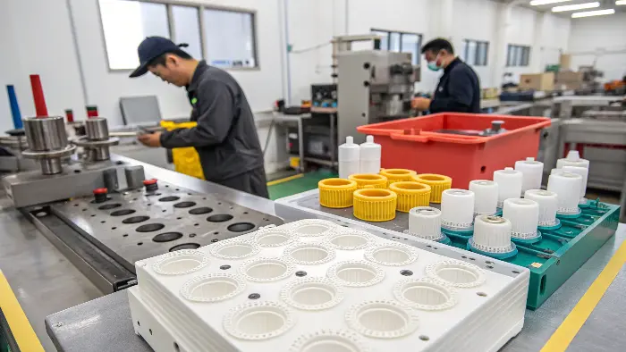
This sounds like a lot to handle, but it’s a skill that distinguishes great designers from good ones. When you are able to read the needs of the molding process, you no longer view manufacturing as a limitation but rather as a collaborator in creation. You have the confidence to break rules because you know how to make your vision happen. Let’s get deeper into the specific techniques that will enable you to master this skill and bring your most ambitious cap designs to reality.
How do you balance innovative cap designs with practical manufacturing constraints?
You’ve spent days perfecting a unique, eye-catching cap design, only to have the production team tell you it can’t be made. This feedback loop is discouraging and can make you feel like your creativity is being stifled by a long list of technical rules. The solution is to learn these rules and use them to your advantage. When you understand the "why" behind manufacturing constraints, you can innovate within them, creating designs that are both bold and buildable.
To successfully balance an innovative design with manufacturing reality, you must embrace Design for Manufacturing (DFM) from your very first sketch. This means thinking about draft angles for easy part ejection, keeping wall thickness uniform to prevent defects, and planning the parting line. The most critical step is to collaborate with your mold maker early and often. Their expert feedback can help you tweak a creative concept to make it perfectly moldable without sacrificing its unique aesthetic.
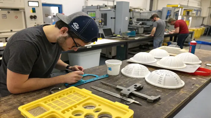
In my years of running a mold and CNC company, I’ve seen this play out time and again. The most successful projects were always the ones where the designer didn’t just hand over a file and hope for the best. Instead, they treated the process like a partnership. Thinking about the practical side of things isn’t a restriction; it’s a tool. It allows you to be more intentionally creative because you’re designing with the final, physical product in mind. Let’s break down how to make this a core part of your workflow.
The Foundation: Design for Manufacturing (DFM)
DFM is not a buzzword; it’s a state of mind. It’s designing a component so that it is as simple and cheap to produce as possible. There are some principles in plastic caps that are absolutely key.
- Draft Angles: All molded parts must be pushed out of the mold. Draft angle is a very slight taper on the vertical sides of the cap to prevent the part from dragging against the mold surface when it is ejected. Without it, you end up with drag marks, poor surface finish, or the part jams. A standard rule of thumb is 1-2 degrees, but it will depend on texture and material.
- Uniform Wall Thickness: This is probably the most important rule. When molten plastic hardens, it shrinks. If some area of your cap is significantly thicker than another, it will shrink and harden differently. This is the cause of problems like sink marks (indentation in the surface area), voids (air bubbles inside), and warping. Attempt to be consistent.
- Parting Line: The line at which the two halves of the mold (cavity and core) intersect. Where the parting line is positioned influences where the gate must be, where the flash (excess plastic) will be, and the look of the cap. A well-designed parting line can conceal witness marks on less visible areas of the cap.
The Power of Early Collaboration
I once worked with a designer, let’s call him Jacky, who had designed a beautiful cap with a sharp, crisp edge. It looked fantastic in the render. But in molding, sharp internal corners create stress points and can be difficult to fill properly. By talking to him before we even started cutting steel, we suggested adding a tiny, almost invisible radius to that corner. This small change made the part much stronger and easier to mold, without changing the design’s intent. This is the power of early collaboration. Bring your mold maker into the conversation as soon as you have a concept. They can spot potential issues and suggest simple solutions that save enormous amounts of time and money later.
| Design Approach | "Creative-First" Design | "DFM-Informed" Design |
|---|---|---|
| Wall Thickness | Varies greatly for aesthetic effect. | Kept as uniform as possible. |
| Edges & Corners | Sharp, 90-degree internal corners. | Small, functional radii on corners. |
| Undercuts | Complex undercuts without thought to release. | Undercuts designed to work with sliders/lifters. |
| Collaboration | Mold maker involved after design is final. | Mold maker consulted during concept phase. |
| Outcome | High risk of defects, redesigns, delays. | Smooth production, lower cost, high quality. |
Types of Plastic Caps
Flip-Top Caps
You use these from your shower routine—shampoo, body wash, or maybe a ketchup bottle. They’re all one-handed thanks to that handy little hinge. Flip-top molds have to get the flexibility and strength of that little hinge just right, which isn’t as simple as it sounds.
Screw Caps
The classics. Screw-on caps on soda bottles, pill bottles, you name it—everywhere because they seal up tight with those trusty threads. The moulds? They must be precise—any error in the threading causes leaks or stuck-on caps, and nobody wants that.
Child-Resistant Caps
Safety is the motto in this case—expect to see push-and-twist containers for drugs or poisons. The packaging will have to be tested to the extreme, childproof but not overly inconvenient for adults to operate.
Dispensing Caps
Look at disc-tops on lotion bottles or trigger sprayers for cleaning liquids. These are used for control, dispensing only the right amount. Their molds are more complex, with moving parts and bizarre shapes, but when executed well, they’re a game-changer.
Tamper-Evident Caps
That tiny snap-off ring that you get when you first pop the bottle open? That’s your guarantee the product is unopened. The molds for these are tiny breakaway pieces, and getting them just so requires a lot of finesse.
Selecting the right cap is all about what you’re packaging, for whom it’s going to be used, and what regulations you must comply with. It’s choosing the right tool for the job, except this tool must be both functional and attractive.
What advanced mold features are essential for complex cap designs?
Your design calls for internal threads, a snap-on feature, and a tamper-evident ring. A simple up-and-down mold won’t work. This is where many designers hit a wall, thinking their ideas are too complex. The problem isn’t your design; it’s that you need a more advanced mold to make it. By understanding the mechanisms that create these features, you can confidently design them into your caps, knowing they can be produced.
For complex caps, advanced mold features are not optional—they are essential. The most common is an unscrewing mechanism, which uses a motor or gears to rotate the core and release threaded caps. For features like snap-fits or side holes, you need sliders and lifters. These are moving parts within the mold that create an undercut and then move out of the way before the part is ejected. For high-volume production, a hot runner system is also key for maintaining quality and speed.
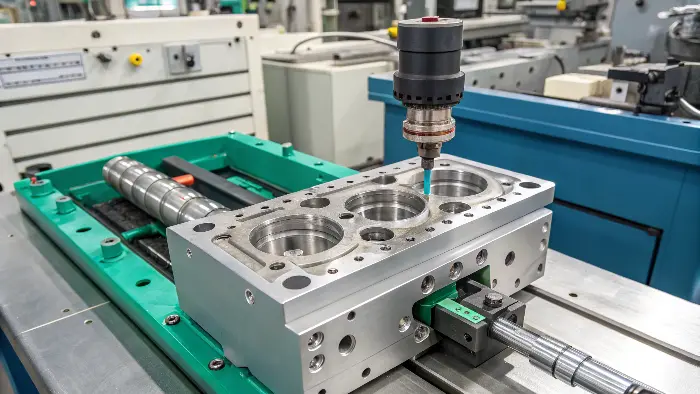
These mechanisms add cost and complexity to the mold, but they are the tools that unlock true design freedom. When I started my journey in a mold factory, I was fascinated by these intricate, moving molds. They were like complex puzzles, and watching them create a perfectly threaded cap in seconds was amazing. Knowing how these systems work allows you to design features that seem impossible at first glance. Let’s look at the most important ones you’ll encounter.
Handling Threads: The Unscrewing Mechanism
Nearly all screw caps need an unscrewing mold. You cannot simply pull a cap off a threaded core; you have to twist it off, just as you would twist off the cap of a bottle. The mold accomplishes that for you.
- How it Works: A machine turns the core that forms the internal thread of the cap prior to the opening of the mold. Once the core is fully released from the plastic threads, the mold opens and pushes out the cap.
- Types of Mechanisms:
- Motor-Driven: A hydraulic or electric motor delivers strong, accurate rotation. Ideal for high-speed, high-volume production.
- Rack and Pinion: A linear gear rack, driven by the motion of the mold openings, turns a pinion gear connected to the core. It’s a mechanical solution that is very reliable.
- Planetary Gear System: More intricate, but enables several cores to be recovered simultaneously in a compact area.
Creating Undercuts: Sliders and Lifters
An undercut is any shape in geometry that will prevent the part from being pushed straight out of the mold cavity. Think of a snap-fit bead on the inside of a cap or a hole on the side. Sliders and lifters are the solution.
- Sliders (or Slides): They are pieces of steel that move in a direction perpendicular to the direction the mold is opening up. They are usually mounted on the side of the mold and are moved into position prior to injection to create the undercut feature. Prior to ejection, they are removed from position, cutting a path for the part to be ejected. They are ideal for larger undercuts on the outside of a part.
- Lifters: These are components used in the ejector system of a mold. When the ejector pins push out the part, the lifter moves and at an angle simultaneously. The angle of movement allows it to form an internal undercut and then leave it as the part is pushed out. They are best suited for small, internal undercuts where a side-action slider cannot be accommodated.
| Feature to Create | Recommended Mold Mechanism | Key Design Consideration |
|---|---|---|
| Internal Threads | Unscrewing Mechanism (Motor or Rack) | Ensure there’s a "lead-out" for the thread to prevent damage. |
| External Side Hole | Slider (Side-Action Core) | The slider’s movement must be clear of other mold components. |
| Internal Snap-Fit Bead | Lifter | The undercut must be designed with enough flex to release from the lifter. |
| Tamper-Evident Ring | Stripper Plate & Forced Ejection | The material must be flexible enough to stretch over the core. |
What are the best plastic materials for high-performance and visually appealing caps?
You’ve designed a stunning cap, but when the first samples arrive, the color is off, it feels flimsy, or it cracks under pressure. The most beautiful design can be ruined by the wrong material choice. This is a common frustration, leading to redesigns and unhappy clients. The solution is to think about material selection as a core part of the design process, not an afterthought. Matching the plastic to the cap’s function and aesthetic is a critical skill.
A cap needs the best plastic, which will not be determined by circumstances at all. In common food-safe caps, Polypropylene (PP) is one of the best options due to chemical resistance and strength to form an entire hinge. Polycarbonate (PC) or PET is superb to get crystal-clear, glass-like cap. In case you require a high-end soft-touch, then you should use an overmolding technique where Thermoplastic Elastomer (TPE) is used. In the case of luxury packaging, additives can be filled in plastics (such as ABS) to produce a metallic or pearlescent effect which will add lots of value.

I’ve helped countless clients navigate the world of plastics. It can seem overwhelming with all the acronyms and technical data sheets. But it boils down to a few key questions: What does the cap need to do? What should it look like and feel like? And what is the budget? Answering these questions will narrow down your options significantly. Let’s explore some of the most common choices and how to use them to elevate your designs.
The Workhorses: Commodity Plastics
These are the most common and cost-effective plastics used for caps. They get the job done reliably for a huge range of products.
- Polypropylene (PP): The king of caps. It has great fatigue resistance, which makes it perfect for flip-top caps with a "living hinge." It’s also very resistant to chemicals and is cost-effective. However, it’s not typically crystal clear.
- High-Density Polyethylene (HDPE): Very similar to PP but a bit softer and more impact-resistant at low temperatures. You’ll find it used for milk jug caps and other industrial closures. It’s tough and cheap.
- Low-Density Polyethylene (LDPE): Much more flexible than HDPE. It’s often used for snap-on lids and closures that need to be pliable.
The Specialists: Engineering and Aesthetic Plastics
When you need higher performance or a specific look, you move into engineering-grade plastics and special formulations.
- Polycarbonate (PC): If you need high clarity and high impact strength, PC is a great choice. It’s used for things like high-end water bottle caps where a glass-like appearance is desired. It is more expensive, though.
- Acrylonitrile Butadiene Styrene (ABS): ABS is known for its toughness and excellent surface finish. It takes color and plating (like chrome) very well, making it a favorite for cosmetic and luxury packaging where a high-gloss, premium look is essential.
- Thermoplastic Elastomers (TPE): This is a class of rubber-like plastics. They are often used in a two-shot molding process (overmolding) to add a soft, grippy layer over a rigid plastic like PP. This is perfect for sport caps or any closure that needs a better feel and seal.
| Plastic Material | Key Properties | Common Cap Application |
|---|---|---|
| PP (Polypropylene) | Chemical resistance, living hinge, low cost. | Flip-top caps, screw caps for food/pharma. |
| HDPE (High-Density Polyethylene) | Tough, low cost, good impact strength. | Milk jug caps, industrial closures. |
| PC (Polycarbonate) | High clarity, high impact strength. | High-end beverage caps, protective covers. |
| ABS | High gloss, good toughness, platable. | Cosmetic caps, luxury packaging. |
| TPE (Thermoplastic Elastomer) | Soft-touch, flexible, good grip. | Overmolded sport caps, soft-touch closures. |
How can you prevent common molding defects in intricate plastic caps?
Your project is moving along, but the first molded caps are a disaster. They’re covered in ugly sink marks, have thin bits of flash around the edges, or are noticeably warped. These defects can bring production to a halt, causing delays and driving up costs with high scrap rates. The key isn’t just fixing these problems; it’s proactively designing your cap and mold to prevent them from ever happening in the first place.
To prevent common molding defects, focus on the root causes in the design phase. Avoid sink marks by ensuring wall thickness is uniform and by placing gates away from thick sections. Prevent flash by designing a flat, robust parting line area and ensuring the mold can handle the injection pressure. Minimize warping by creating symmetrical designs where possible and planning for uniform cooling channels within the mold. Using mold flow simulation software is the best way to predict and solve these issues before cutting steel.
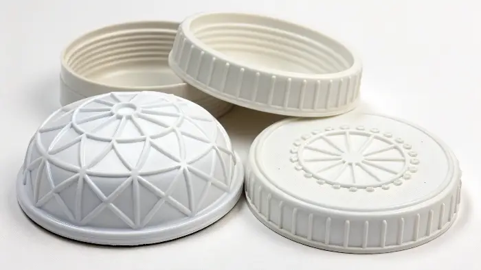
In my factory, we live by the rule: "An hour of simulation saves a week of rework." I’ve seen designers like Jacky, who are sharp and creative, get frustrated by these physical-world problems. But these defects aren’t random. They are predictable results of pressure, temperature, and geometry. By understanding this relationship, you can design defensively and ensure your parts come out perfectly, saving everyone time and headaches.
The Big Three Defects and How to Beat Them
While there are dozens of potential defects, three of them cause the most trouble for cap designs.
-
Sink Marks: These are small depressions or craters on the surface of the cap.
- Cause: They happen when a thick section of plastic shrinks more than the surrounding thinner areas, pulling the surface inward as it cools. Ribs or bosses on the underside of a cap are common culprits.
- Prevention: The number one rule is uniform wall thickness. If you need a rib for strength, design it to be no more than 50-60% of the thickness of the main wall it’s attached to. Also, place the gate far from these thick areas.
-
Flash: This is a thin, unwanted film of plastic that squeezes out of the mold at the parting line or around ejector pins.
- Cause: The clamp force of the molding machine isn’t strong enough to hold the mold shut against the injection pressure, or the parting line surfaces don’t seal perfectly.
- Prevention: This is partly a processing issue, but you can help in the design phase. Ensure your cap’s parting line is as simple and flat as possible. Complex, multi-level parting lines are much harder to seal.
-
Warping: This is when the cap twists or bends out of its intended shape as it cools.
- Cause: Uneven cooling and non-uniform shrinkage. If one side of the cap cools much faster than the other, the different rates of shrinkage will create internal stresses that warp the part.
- Prevention: Design for symmetry whenever you can. If the part is asymmetrical, work with the mold maker to design a strategic cooling layout, with cooling channels placed to ensure the entire part cools at an even rate.
Your Secret Weapon: Mold Flow Simulation
For any designer working on complex parts, mold flow analysis software is a game-changer. This software simulates the injection molding process on your 3D model. It can predict exactly how the plastic will flow into the mold, where air traps might occur, how the part will cool, and—most importantly—where defects like sink marks and warping are likely to appear. I always encourage the designers I work with to request a mold flow analysis. It allows you to see problems and fix them in the digital stage, which is infinitely cheaper and faster than fixing them in the physical tool.
| Defect | Primary Cause | Design / Process Solution |
|---|---|---|
| Sink Marks | Non-uniform wall thickness. | Maintain uniform walls; core out thick sections. |
| Flash | Poor parting line seal; high injection pressure. | Design a simple, flat parting line; ensure adequate clamp tonnage. |
| Warping | Differential shrinkage; non-uniform cooling. | Design symmetrical parts; plan for strategic cooling channels. |
| Short Shot | Incomplete filling of the mold cavity. | Increase wall thickness; add air vents; use mold flow to check fill pattern. |
Conclusion
Achieving plastic cap molds is not like memorizing a thousand rules. It is not the framework of a change of thinking. It is the very aspect of looking at design and manufacturing as the two sides of one coin. A combination of creativity and DFM through the utilization of advanced part features in molds, selecting of the appropriate materials, and taking a proactive of eliminating defects can turn your packaging around. You shift the position of being a designer who hopes that his work can be made to him being one who stipulates on how his work will be done.
