
Introduction: Why Wall Thickness Matters in Injection Molding
I still remember my first encounter with a warped plastic part fresh out of the mold. It was supposed to be a sleek electronic housing, but uneven cooling had twisted it into something resembling modern art, not exactly what the client had in mind. That moment taught me a critical lesson: wall thickness isn’t just a number on a spec sheet; it’s the backbone of injection molding success.
Whether you’re designing a razor-thin medical device or a rugged automotive component, understanding the differences between thin-wall and thick-wall injection molding is crucial. It affects everything from material selection and cooling rates to production speed and final part quality.
In this guide, we’ll dive deep into:
✔ Key differences between thin and thick-walled molding
✔ Material considerations for optimal performance
✔ Design guidelines to avoid warping, sink marks, and short shots
✔ Process optimizations for faster cycles and lower costs
✔ Real-world insights from my years in the industry
Let’s get started.
1. Thin-Wall vs. Thick-Wall Molding: Core Differences
Defining Thin-Wall and Thick-Wall Molding
- Thin-Wall Molding: Typically refers to parts with walls <1 mm (or a flow length-to-thickness ratio >150). Common in electronics, packaging, and medical devices.
- Thick-Wall Molding: Involves walls >4 mm, often used in structural components like automotive housings or industrial containers.
Key Process Differences
| Factor | Thin-Wall Molding | Thick-Wall Molding |
|---|---|---|
| Injection Pressure | High (200+ MPa) | Moderate (50–150 MPa) |
| Cooling Time | Short (seconds) | Long (minutes) |
| Cycle Time | Fast (3–10 sec) | Slow (30+ sec) |
| Material Flow | Requires high-MFI plastics | Tolerates lower-MFI materials |
“Thin-wall molding is like sprinting—you need speed and precision. Thick-wall molding is a marathon, demanding patience to avoid defects.”
Why Thin-Wall Molding Demands Higher Pressure
- Thin cavities resist flow, requiring high-speed injection (up to 2,000 mm/s) to fill before cooling starts.
- Short shots are a constant risk if pressure isn’t optimized.
Why Thick-Wall Parts Cool Slower
- Heat dissipates slowly in thicker sections, leading to:
- Sink marks (from uneven shrinkage)
- Voids (trapped air in the core)
- Warping (differential cooling stresses)
2. Material Selection: What Works Best?
Thermal Conductivity & Flow Matter
- Thin-Wall Friendly Materials:
- Polypropylene (PP) – High melt flow index (MFI >30)
- ABS – Balances flow and toughness
- Liquid Crystal Polymers (LCP) – Exceptional for ultra-thin parts
- Thick-Wall Friendly Materials:
- Nylon (PA6, PA66) – Resists warping
- Polycarbonate (PC) – High impact strength
- PEEK – For high-temp applications
Material Comparison Table
| Material | Max Flow Ratio | Ideal Wall Thickness (mm) | Best For |
|---|---|---|---|
| ABS | 30–50 | 1.0–3.5 | Consumer electronics |
| PP | 200–300 | 0.6–4.5 | Packaging, containers |
| PC | 30–100 | 1.5–9.3 | Automotive, lenses |
| Nylon | 140–340 | 0.4–3.2 | Industrial parts |
“I once used PC for a thin-wall medical device—big mistake. The viscosity caused short shots until we switched to a high-flow LCP.”
3. Design Guidelines for Thin-Wall Parts
Rule #1: Uniform Wall Thickness
- Avoid abrupt changes (leads to warping).
- Transition gradually (use 3:1 taper ratio).
Rule #2: Reinforce with Ribs
- Rib thickness = 40–60% of the main wall
- Height ≤ 3x wall thickness
Rule #3: Optimize Gates & Runners
- Multi-gate designs improve fill balance.
- Hot runners reduce material waste.
Rule #4: Draft Angles Are Non-Negotiable
- Minimum 0.5°–1° draft for easy ejection.
“A client ignored draft angles on a 0.8-mm housing. The result? Scrapped parts and a $10,000 mold rework.”
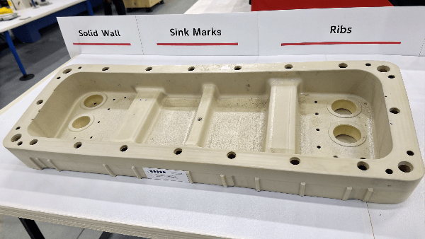
4. Thick-Wall Design: Avoiding Sink Marks & Voids
Problem: Sink Marks
- Cause: Thick sections cool slower, pulling material inward.
- Fix:
- Use ribs instead of solid walls.
- Reduce thickness where possible.
Problem: Voids
- Cause: Trapped air in the core.
- Fix:
- Gas-assist molding for hollow sections.
- Mold venting to release trapped air.
Problem: Warping
- Cause: Uneven cooling stresses.
- Fix:
- Conformal cooling channels in the mold.
- Post-mold annealing for stress relief.
5. Machine & Process Optimization
Thin-Wall Molding Machines
- High-speed injection (1,000+ mm/s)
- Clamping force ≥ 5–8 tons/inch² (vs. 3–5 tons for thick-wall)
- Servo-driven hydraulics for precision
Thick-Wall Molding Machines
- Higher tonnage to handle prolonged pressure.
- Slow injection to prevent jetting.
Cooling Strategies
| Method | Thin-Wall | Thick-Wall |
|---|---|---|
| Cooling Channels | Straight, close to surface | Conformal, deep channels |
| Coolant Temp | 10–20°C | 40–60°C (slower cooling) |
“We cut cycle times 30% on a thick-wall gear by switching to conformal cooling. The mold cost more upfront but paid for itself in 3 months.”
6. Real-World Defects & Fixes
| Defect | Likely Cause | Solution |
|---|---|---|
| Short shots | Low pressure/material flow | Increase injection speed, use high-MFI material |
| Sink marks | Thick sections cooling unevenly | Add ribs, reduce wall thickness |
| Warping | Non-uniform cooling | Improve cooling layout, anneal parts |
Conclusion: Key Takeaways
- Thin-wall molding demands high speed, high pressure, and high-flow materials.
- Thick-wall molding requires slow cooling, uniform thickness, and stress management.
- Design for manufacturability (DFM) is non-negotiable—avoid sharp corners, uneven walls, and inadequate draft.
- Material choice makes or breaks your part—don’t just default to ABS or PC.
- Process optimization (cooling, gating, clamping) is where cost savings hide.
At CKMOLD, we’ve seen projects fail (and succeed) based on these principles. Whether you’re prototyping or scaling production, getting wall thickness right from the start saves time, money, and frustration.
Need help optimizing your design? Let’s talk.