Injection pressure in injection molding is a fine balancing act. Too low, and your parts will not fill up correctly, and you’ll be stuck with annoying defects. Too high, and you’ll flash the mold or worse, destroy it, and be confronted with expensive repairs and downtime. This vital parameter is not well understood, but it is essential to producing quality molded product on a day-in, day-out basis.
Injection pressure in injection molding is the pressure used by the reciprocating screw to force the molten plastic material into the mold cavity. It is a decisional variable that decides the quality of the end product, with influencing parameters such as dimensional accuracy, material flow, and correct filling of the mold.
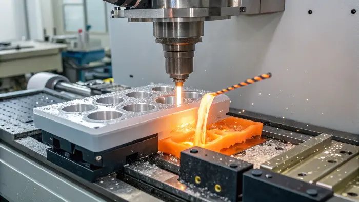
As my experience indicates, this pressure is no small thing. When I initially began CKMOLD, assisting clients in understanding these fundamental principles was most important because it has a direct implication on their success. But it is not sufficient to know what it is. For designers such as Jacky, who must make sure that their designs can be manufactured and are of quality, a more in-depth understanding is necessary. So, let’s explore this critical parameter a little further.
What should injection pressure be?
You’ve got a part drafted, and the time for molding has arrived, but how much pressure does injection need to be? Set it too low, and you get half-finished parts or surface defects. Turn it up too high, and you might get flash or even stress the mold out. It’s an issue that will have you speculating and perhaps wasting time and material on the way to discovering that perfect spot.
There’s no single correct injection pressure. It varies significantly based on the plastic material you have used in its manufacturing, the complexity and wall thickness of the part design, and the design of the mold itself . Optimal pressure ensures complete filling and good part quality without causing defects or damaging the mold.
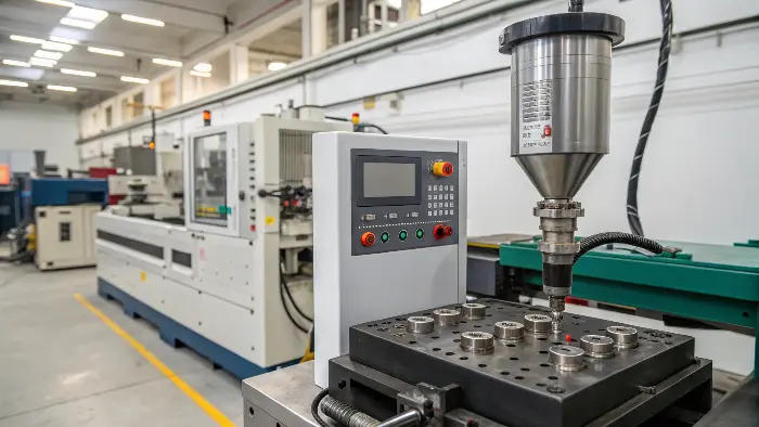
Finding the right injection pressure is often an iterative process, something I learned through years of experience on the factory floor and later helping clients optimize their molding processes. It’s more art and science combined than a fixed value you look up in a book.
Several key factors influence what the injection pressure should be:
- Material Viscosity:
Different plastics have different flow properties. High-viscosity materials (thicker, like molasses) require more pressure to flow into the mold cavity than low-viscosity materials (thinner, like water). Material data sheets might provide a processing window, but real conditions will be different. - Part Design:
- Wall Thickness: Walls that are thinner require higher pressure to fill because the flow path is more restricted.
- Flow Length: The more distance the plastic must travel from the gate to the end of the cavity, the greater pressure will be required to overcome flow resistance.
- Complexity: The features with small details, ribs, or bosses may need to be pressed harder so that all the features are completely filled.
- Mold Design:
- Gate Size and Type: Small gates are more resistant and therefore more pressure is required. The gate type (e.g., pin gate, submarine gate, fan gate) also influences flow.
- Runner System: Longer or narrower runner systems will cause pressure drops, i.e., higher initial injection pressure is necessary at the machine nozzle.
- Venting: Poor venting can trap air, creating back pressure that resists the flow of plastic, effectively requiring higher injection pressure to overcome.
- Mold Temperature: A hotter mold generally reduces the plastic’s viscosity, so it allows it to flow more easily, potentially it requires less injection pressure. A colder mold might require more pressure.
The process technician will start with a pressure setting based on experience or material supplier recommendations and then adjust it based on how the parts are forming. They’ll look for complete filling without flash. This is often part of a "process window" development.
Principles of Setting Injection Speed
- The surface speed of the fluid should be constant.
- Rapid injection to avoid freezing of the melt during injection.
- Injection speed settings should allow for high-speed filling in areas of high importance (i.e., runners) but slow down at the gate.
- Close the mold cavity and stop immediately to avoid overfilling, flash, and residual stress.
- Speed segmentation should take into account mold geometry, secondary flow limitations, and instability conditions.
Proper setting of speed requires a proper knowledge of injection molding materials and processes. As melt flow speed is hard to measure directly, it is possible to estimate indirectly by measuring the screw advance speed or the cavity pressure.
How is Injection Pressure Calculated?
Many designers, especially those new to injection molding, wonder if there’s a straightforward formula to calculate the exact injection pressure needed for their part. It would be great if it were that simple, but trying to guess or use a generic formula often leads to a lot of trial and error on the shop floor. This can be frustrating when you’re trying to get production up and running smoothly.
Injection pressure isn’t typically "calculated" with a simple mathematical formula by designers or machine operators for each specific part. Instead, it’s a parameter set on the injection molding machine, often based on the machine’s hydraulic pressure capabilities and its intensification ratio. Mold flow simulation software can predict required pressures during the design phase, but final settings are usually fine-tuned empirically on the machine.
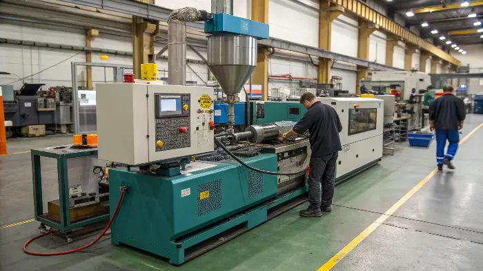
When I was learning the ropes, I quickly realized that "calculating" pressure in the academic sense isn’t how it works day-to-day. It’s more about understanding the machine’s capabilities and observing the results.
Here’s a breakdown of how it’s approached:
- Hydraulic Pressure vs. Plastic Pressure: The injection molding machine uses a hydraulic system (or sometimes an electric servo motor) to push the screw forward. The pressure set on the machine controller is usually the hydraulic pressure.
- Intensification Ratio: There’s a mechanical advantage between the hydraulic cylinder pushing the screw and the screw tip pushing the plastic. This is called the intensification ratio. For example, if the hydraulic cylinder area is 10 times larger than the screw tip area, the intensification ratio is 10:1. This means that 100 bar of hydraulic pressure would result in 1000 bar of plastic pressure at the screw tip (assuming no losses). This ratio is specific to each machine.
Plastic Pressure = Hydraulic Pressure × Intensification Ratio
- Machine Setting: The operator sets the desired hydraulic pressure on the machine. The machine then tries to achieve this pressure during the injection phase.
- Mold Flow Simulation: Before a mold is even built, sophisticated software like Moldflow, Moldex3D, or SolidWorks Plastics can simulate the injection process. These programs can predict the pressures required to fill the part based on its geometry, material properties, and proposed gate locations. This is incredibly valuable for designers like Jacky to optimize part design for moldability and identify potential issues early on. I always recommend this for complex parts.
- Empirical Fine-Tuning: Even with simulations, the actual pressure settings are almost always fine-tuned on the machine. The technician will start with a calculated or recommended pressure (often from the material supplier or simulation) and then adjust it up or down based on:
- Whether the part is filling completely (no short shots).
- Whether there is any flash (indicating too much pressure or poor mold clamping).
- The appearance and dimensions of the part.
So, while there isn’t a simple A + B = C formula for everyday use, the machine’s intensification ratio is a key "calculation" that links the set hydraulic pressure to the actual plastic pressure. The rest is a combination of simulation, experience, and careful observation.
Improving Product Defects with Injection Speed
Flash
Speed control at end of injection can prevent or minimize flash, scorch, and trapped air. End-of-filling deceleration can prevent over-filling of the cavity and eliminate flash and minimize residual stress. Trapped air resulting from inadequate venting at the end of the mold flow path or filling problems can be prevented by slowing down venting, particularly at the injection end.
Short shots
Over-slow gate speeds or localized blockage of flow results in Short shots due to solidification of the melt. The problem may be relieved by a reduction in injection speed immediately after going through the gate or at the site of localized flow blockage. Flow marks, gate burn marks, and delamination in heat-sensitive materials are created by excessive shear in going through the gate.
Splay Mark
Smoothness of the parts is a function of the injection rate; the most important among these are glass fiber-reinforced materials, especially nylon. Splay (waviness) is due to flow instability due to variation in viscosity. Whether waviness or an unpredictable mist is a function of the degree of flow instability.
Sink Mark
Sink mark is minimized by improved pressure transfer and reduced pressure drop. Low mold temperature and low screw advance speed strongly decrease the flow length, which must be compensated by high injection speed. Heat loss is reduced by high-speed flow and, due to high shear heat produced by friction, leads to an increase in melt temperature, slowing down the thickening rate in the outer part layers.
Jetting mark
To avoid jetting, the injection speed setting should permit a quick filling of the runner space and then slow travel through the gate. The position of this transition in speed is important. High-pressure, high-velocity injection needs to take place at small gates, thus becoming a significant source of flow defects.
What is the actual injection pressure?
When you set an injection pressure on the machine, say 1000 psi hydraulic, you might assume that’s the exact pressure the plastic experiences inside the mold cavity. However, this isn’t quite the case, and this misunderstanding can lead to confusion when troubleshooting filling problems or analyzing part quality. The pressure the plastic sees changes as it travels from the nozzle to the furthest point in the cavity.
The "actual" injection pressure experienced by the plastic changes along its flow path. The pressure set on the machine is typically hydraulic pressure, which is converted to a higher plastic pressure at the nozzle via the intensification ratio. However, this plastic pressure then decreases due to friction and cooling as it flows through the nozzle, sprue, runners, gates, and finally into the mold cavity. The pressure inside the cavity is always lower than the initial plastic pressure at the nozzle.
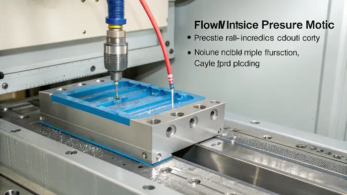
Understanding this pressure drop is something I often explain to clients because it’s crucial for diagnosing issues. Think of it like water flowing through a long, winding garden hose – the pressure at the end of the hose is always less than the pressure at the tap.
Here’s a more detailed look:
- Pressure at the Nozzle (Peak Plastic Pressure): This is the highest pressure the plastic experiences, occurring right as it’s about to be injected from the machine nozzle. It’s the hydraulic pressure multiplied by the machine’s intensification ratio.
- Pressure Losses: As the molten plastic flows, it loses energy (and thus pressure) due to several factors:
- Frictional Losses: Rubbing against the walls of the nozzle, sprue, runners, and cavity.
- Viscous Losses: The inherent resistance of the material to flow.
- Cooling: As the plastic touches the cooler mold surfaces, it starts to solidify, increasing its viscosity and resistance to flow.
- Geometric Restrictions: Sharp turns, changes in cross-sectional area (like going through a small gate) cause significant pressure drops. The gate is often the point of highest pressure drop.
- Cavity Pressure: This is the pressure of the plastic inside the mold cavity. It’s what directly forms the part and packs it out. Cavity pressure is typically much lower than the peak plastic pressure at the nozzle. For example, if the plastic pressure at the nozzle is 15,000 psi, the pressure at the end of fill in the cavity might only be 3,000-5,000 psi, or even less, depending on the part and mold design.
- Measuring Cavity Pressure: For critical applications, sensors can be placed directly within the mold cavity to measure the actual plastic pressure during injection and packing. This provides invaluable data for process control and quality assurance. I’ve seen these sensors save projects by providing clear insights into what’s happening inside the closed mold.
Understanding that the pressure you set on the machine isn’t what the plastic experiences throughout the mold is key. It helps explain why a part might not fill even if the machine pressure seems high – the losses along the flow path could be excessive.
What is the effect of injection pressure on part quality?
Injection pressure isn’t just a machine setting; it’s a powerful lever that directly shapes the quality of your molded parts. If the pressure is off, you can end up with a whole host of problems, from parts that don’t look right to parts that don’t perform as intended. This can be a major source of frustration and cost if not managed correctly.
Injection pressure significantly impacts part quality by influencing how the mold cavity fills and how the material is packed. Insufficient pressure can lead to short shots, sink marks, voids, and poor surface detail. Excessive pressure can cause flash, overpacking (leading to high internal stresses and warpage), and even damage to the mold or machine.
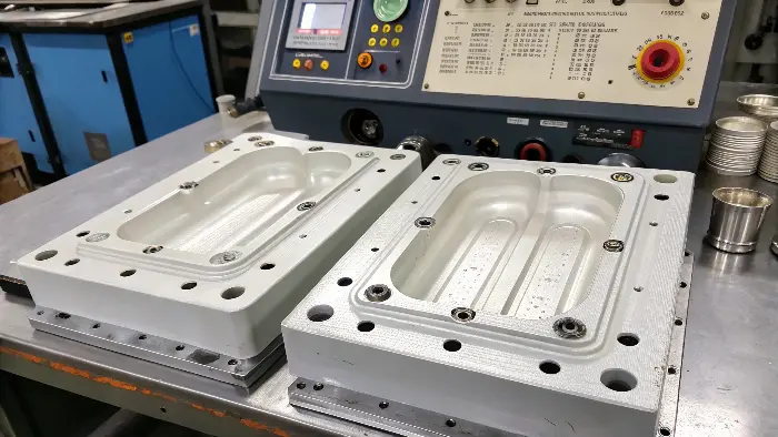
I’ve spent countless hours on factory floors observing how adjustments in injection pressure can transform a problematic part into a perfect one. It’s one of the most critical parameters to get right.
Let’s break down the effects:
Effects of Insufficient Injection Pressure:
- Short Shots/Non-Fills: The most obvious result. The plastic doesn’t have enough force behind it to completely fill the mold cavity, especially thin sections or areas far from the gate.
- Sink Marks: After the initial fill, if the packing pressure (a phase of injection pressure) is too low, the material can shrink away from the mold surface as it cools, especially in thicker areas, causing depressions.
- Voids: Similar to sink marks, but these are internal cavities that form when there isn’t enough material packed in to compensate for shrinkage during cooling.
- Poor Surface Replication: Details from the mold surface (like texture or fine features) may not be sharply reproduced if the pressure isn’t high enough to force the plastic into every nook and cranny.
- Prominent Weld Lines: If flow fronts meet with insufficient pressure, they may not fuse together properly, resulting in weak and visible weld lines.
- Dimensional Instability: Parts may be undersized or have inconsistent dimensions.
Effects of Excessive Injection Pressure:
- Flash: The most common sign. The high pressure forces molten plastic out of the cavity along the parting line or around ejector pins.
- Overpacking: Too much material is forced into the cavity. This can lead to:
- High Internal Stresses: Making the part brittle or prone to cracking later.
- Warpage: Due to uneven stress relief during cooling.
- Ejection Difficulties: The part sticks in the mold.
- Dimensional Issues: Parts may be oversized.
- Mold Damage: In extreme cases, excessive pressure can deflect mold components, damage delicate core pins, or even hob the cavity surfaces.
- Machine Wear: Consistently running at very high pressures can put extra strain on the injection molding machine components.
- Material Degradation: High pressure can sometimes contribute to increased shear, potentially degrading the material.
Here’s a table summarizing the impact:
| Pressure Level | Potential Positive Effects (if optimal) | Potential Negative Effects (if too low/too high) |
|---|---|---|
| Too Low | – | Short shots, sink marks, voids, poor surface detail, weak weld lines, undersized |
| Optimal | Complete fill, good packing, dimensional accuracy, good surface finish, strong weld lines | – |
| Too High | Can help fill very thin sections (sometimes) | Flash, overpacking, internal stress, warpage, ejection issues, mold/machine wear |
Finding that "Goldilocks" pressure – not too low, not too high, but just right – is essential for consistent, high-quality parts.
What is the difference between injection pressure and back pressure?
In the world of injection molding, you’ll often hear "injection pressure" and "back pressure" mentioned, sometimes in the same breath. It’s easy to get them confused, but they are distinct parameters that control different aspects of the molding cycle. Mixing them up can lead to incorrect machine adjustments and ultimately affect your part quality.
Injection pressure is the primary force the screw applies to push molten plastic forward into the mold cavity during the injection and packing phases. Back pressure, on the other hand, is a controlled resistance applied to the screw as it rotates and retracts (plasticizes) to prepare the next shot of material. They serve different purposes and occur at different stages of the molding cycle.
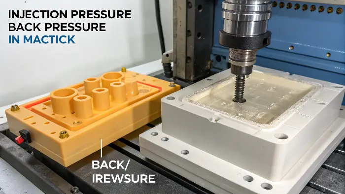
I always make sure to clarify this distinction when I’m training people or helping clients troubleshoot. Understanding their separate roles is fundamental to good process control.
Let’s look at each one more closely:
Injection Pressure:
- Purpose: To fill the mold cavity with molten plastic and then to pack additional material into the cavity to compensate for shrinkage as the plastic cools and solidifies.
- When it Occurs: During the injection (fill) phase and the packing (hold) phase of the molding cycle. The screw moves forward like a piston.
- Primary Effects: Determines if the part fills completely, influences part dimensions, surface finish, and can cause defects like short shots or flash if not set correctly.
- Setting: Typically set as a hydraulic pressure on the machine, which translates to plastic pressure via the intensification ratio.
Back Pressure:
- Purpose:
- Melt Homogeneity: It creates a more consistent and uniform melt by ensuring the screw flights are always full of material, improving mixing.
- Additive/Colorant Dispersion: Helps to better disperse colorants, fillers, or other additives within the molten plastic.
- Volatile Removal: Can help to vent out trapped air or moisture from the melt before it’s injected.
- Consistent Shot Size: Helps achieve a more precise and repeatable shot volume.
- When it Occurs: During the screw recovery (plasticizing) phase, as the screw rotates and moves backward to draw in new material for the next shot. It’s a resistance applied against this backward movement.
- Primary Effects: Affects melt quality, color consistency, and can influence cycle time.
- Too Low: May result in inconsistent melt, poor color dispersion, splay (due to moisture/volatiles), or inconsistent shot size.
- Too High: Can cause material degradation due to excessive shear heating, increase screw recovery time (lengthening the cycle), and put extra wear on the screw and barrel.
- Setting: Also set as a hydraulic pressure on the machine, but it’s a much lower value than injection pressure (e.g., 50-300 psi hydraulic back pressure compared to 500-2000 psi hydraulic injection pressure).
Here’s a simple table to highlight the differences:
| Feature | Injection Pressure | Back Pressure |
|---|---|---|
| Action | Pushes material into the mold (screw moves forward) | Resists screw retraction during plasticizing (screw rotates & moves back) |
| Primary Goal | Fill and pack the mold cavity | Prepare a homogeneous melt for the next shot |
| Timing | Injection & Packing phases | Screw Recovery (Plasticizing) phase |
| Magnitude | High | Low to Moderate |
| Key Impacts | Part filling, dimensions, flash, sinks | Melt quality, color dispersion, cycle time, material degradation |
While both are pressures related to the screw, they control very different aspects of the injection molding process. Getting both set correctly is vital for producing high-quality parts efficiently.
Conclusion
Managing and understanding injection pressure correctly is flat out essential to injection molding. It’s the pressure that shapes your product, determining everything from full fill to finish size and surface finish. As we’ve discovered, it’s not a number, but a dynamic one based on material, part design, and mold properties. Recognizing its nuances, and associated parameters like back pressure, is the key to making consistent, high-quality parts and the art of molding mastery.
