
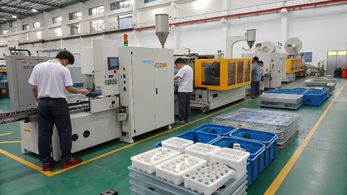
Are your plastic parts too heavy, costly, or time-consuming to produce? Traditional molding might be holding you back. Imagine lighter, quicker, and more efficient manufacturing. Thin wall injection molding gives you the tools to make it a reality, transforming your production process.
Thin-wall injection molding is a production strategy for reducing part mass or creating compact packaging, housings and components while maintaining function. The challenge is not thickness alone; flow length, gate, resin viscosity, injection rate, venting, mold temperature, cooling and ejection combine to determine whether the part fills and remains stable.
Related CKMOLD resources: DFM analysis, rapid tooling, production injection molding.
Thin wall injection molding is a unique process employed for the production of plastic parts of very thin wall thicknesses of less than 1mm. It needs high precision, high shot speed, and special equipment and materials. It enables large material savings, reduced cycle time, and production of light high-performance parts, and hence is adaptable to the requirements of present manufacturing demand.
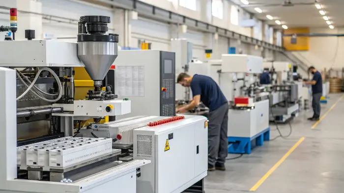
I have witnessed firsthand how thin wall knowledge can provide you with an actual business advantage. It’s not merely thickness reduction; it’s waste reduction. If you’re willing to look at how this technology can make your project easier, let’s get into the details. There is a lot to know, and a sure understanding of the subtleties is the secret to success.
What Exactly Defines Thin Wall Injection Molding and Its Benefits?
Struggling with material waste and long cycle times in your plastic manufacturing? These can consume margins and slow down innovation. Thin wall injection molding puts an end to these problems by maximizing material usage and accelerating production.
Thin wall injection molding refers to producing plastic parts with wall thicknesses typically ranging from 0.5mm to 1mm, though some applications go even thinner. The key benefits include significant material cost reduction, faster cooling and cycle times. These benefits further leading to higher productivity, and lighter end products, which can reduce shipping costs and improve product performance.
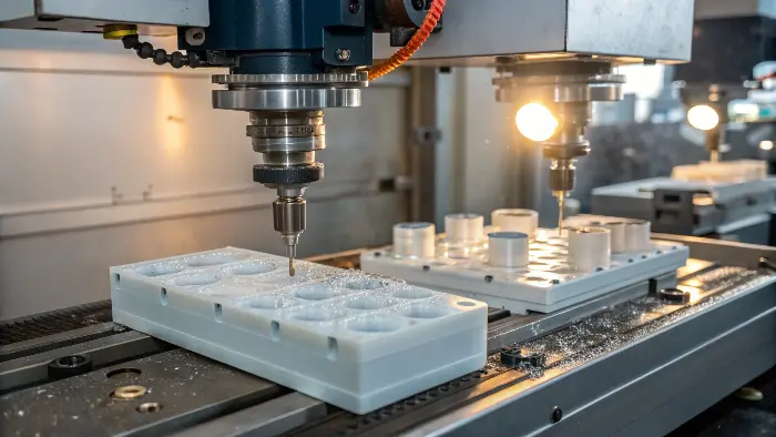
When we talk about “thin wall,” it’s not just a loose term. It’s generally defined by the flow-length-to-thickness ratio (L/T ratio). A part is often considered thin-walled if its L/T ratio is greater than 100, or if its wall thickness is less than 1mm.
This shift brought several advantages:
- Material Savings: This is the most obvious one. Less plastic per part means lower material costs. For high-volume production, this adds up significantly. Imagine producing millions of parts; even a small reduction per part translates to huge savings.
- Faster Cycle Times: Thinner walls cool down much faster. This drastically reduces the cooling phase, which is often the longest part of the injection molding cycle. Faster cycles mean more parts per hour, increasing overall equipment effectiveness.
- Reduced Part Weight: Lighter parts are cheaper to ship and can improve the user experience for portable products. Think about consumer electronics or medical devices where weight is a critical factor.
- Design Freedom: Sometimes, thin walls are a design necessity for compact products or for achieving specific aesthetic goals. It allows for more intricate and space-efficient designs.
However, achieving these benefits requires careful consideration of the entire process, from part design to material selection and machine capabilities. It’s a more demanding process than conventional molding, requiring higher precision and control.
What Are the Key Design Considerations for Successful Thin Wall Parts?
Are your thin wall part designs not performing as needed in service or in molding? Poor design choice can lead to failure points, warpage, or insufficient fill. Proper design is critical to the manufacturability and soundness of thin-walled parts.
Key design considerations for thin wall parts include maintaining uniform wall thickness to ensure consistent flow and cooling. Incorporating ribs and gussets strategically can add strength without increasing overall thickness. Generous draft angles are essential for easy part ejection, and smooth transitions between different thicknesses prevent stress concentrations. Gate location is also crucial for optimal melt flow.
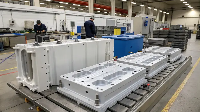
Here are some critical design aspects I generally emphasize:
- Uniform Wall Thickness: This is paramount. Variations in thickness can cause uneven cooling, leading to warpage and internal stresses. If thickness changes are unavoidable, make them gradual, like a gentle slope rather than a step.
- Ribs and Gussets: Instead of making the entire wall thicker for strength, use ribs. Ribs should typically be 50-60% of the nominal wall thickness to avoid sink marks on the opposite surface. Gussets can reinforce corners and bosses effectively.
* Draft Angles: Because thin parts shrink tightly onto the core, you need more draft than with thicker parts. I usually recommend at least 1 to 2 degrees per side, sometimes more for textured surfaces or deeper draws. This makes part ejection much smoother.
- Gate Location and Type: The gate needs to be positioned to fill the thinnest sections first and to minimize flow length. Hot runner systems are often preferred for better control, reduced material waste from sprues, and faster cycle times. Multiple gates might be needed for larger parts.
- Material Flow: Consider how the plastic will flow and avoid sharp corners that can restrict flow or create weld lines in critical areas. Use generous radii to promote smooth, uninterrupted flow.
- Venting: Trapped air is a big enemy in thin wall molding. Ensure adequate venting in the mold, often along the parting line and near the end of fill. It allows air to escape as the cavity fills rapidly.
Which Materials Are Best Suited for Thin Wall Injection Molding?
Choosing the wrong material for your thin wall application can lead to brittle parts. Material properties are magnified in thin sections. Selecting a resin with the right flow characteristics and strength is vital for success.
Materials best suited for thin wall injection molding typically have high melt flow rates (MFR) for easy filling of thin cavities. Polypropylene (PP), polyethylene (PE), polystyrene (PS), and ABS are common choices. Engineering plastics like polycarbonate (PC) or nylon (PA) can also be used, often with flow enhancers, when higher strength or temperature resistance is needed.
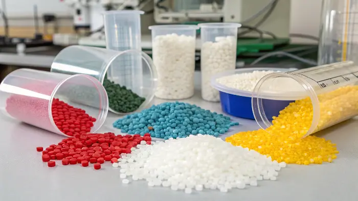
Material selection is a critical step. Not all plastics are created equal when it comes to thin wall applications. The primary characteristic you’re looking for is a high melt flow rate (MFR) or melt flow index (MFI). This indicates how easily the molten plastic can flow through the narrow cavities under pressure. A higher MFR generally means the material can fill complex, thin sections more readily before it cools and solidifies.
Here’s a breakdown of common material choices and why:
| Material | Key Characteristics for Thin Wall Molding | Common Applications |
|---|---|---|
| Polypropylene (PP) | Excellent flow, good chemical resistance, low cost, good fatigue resistance. | Food containers, packaging, caps, hinges |
| Polyethylene (PE) | Good flow (especially HDPE, LLDPE), flexibility, low cost, good impact strength. | Lids, caps, flexible packaging, bottles |
| Polystyrene (PS) | Easy to process, good clarity (GPPS), good stiffness (HIPS), low cost. | Disposable cutlery, cups, food trays |
| ABS | Good impact strength, good dimensional stability, can be easily processed. | Electronic housings, toys, enclosures |
| Polycarbonate (PC) | High impact strength, good temperature resistance, optical clarity. May need flow aids. | Medical devices, lenses, phone cases |
| Nylon (PA) | Good strength and toughness, chemical resistance. Often requires drying. | Automotive parts, gears, connectors |
| Acetal (POM) | High stiffness, low friction, excellent dimensional stability. | Precision parts, gears, bearings |
When I’m advising clients, Reviewers should ask about the end-use application. Does it need to be food-grade (like PP or PE)? Will it be exposed to chemicals or high temperatures (like PC or PA)? Does it need to withstand impact (like ABS or PC)? These questions help narrow down the material choices.
We, I and my client, consider specialized grades of these polymers. These grades are specifically formulated for thin wall molding. They offer enhanced flow properties and better mechanical performance. Additives like flow enhancers, or nucleating agents can also play a crucial role. They play a role in optimizing the material for the demanding thin wall process.
What Are the Common Challenges in Thin Wall Injection Molding and How Can We Overcome Them?
Facing issues like incomplete fills, warping, or part ejection in your thin wall molding process? These challenges are common but can derail production. Understanding these hurdles is the first step to implementing effective solutions and achieving consistent quality.
Common challenges in thin wall injection molding include short shots (incomplete filling), warping due to differential shrinkage, air traps, and difficulties with part ejection. Overcoming these involves optimizing process parameters like injection speed and pressure, ensuring robust mold design with proper venting and cooling, and selecting appropriate high-flow materials.
Thin wall injection molding is definitely not a “set it and forget it” process. It pushes the boundaries of both materials and machinery. I’ve encountered my fair share of challenges over the years, but with careful planning, robust tooling, and precise process control, they are manageable.
Here are some of the most frequent issues and how we typically address them:
- Short Shots (Incomplete Fills): This happens when the molten plastic doesn’t completely fill the mold cavity before it solidifies.
- Solutions: Increase injection speed and pressure (often requiring high-speed injection machines). Ensure the material has a sufficiently high MFR. Check for adequate venting in the mold. Increase melt temperature (within the material’s recommended processing window). Optimize gate size and location for better flow.
- Warpage: Thin parts are very susceptible to warping due to uneven cooling and differential shrinkage.
- Solutions: Ensure uniform wall thickness in the part design. Optimize cooling channel layout in the mold for even and rapid temperature distribution. Adjust packing pressure and time carefully. Select materials with low and uniform shrinkage characteristics. Sometimes, post-molding cooling fixtures are needed to hold the part’s shape.
- Air Traps/Burn Marks: Rapid filling can trap air, leading to voids, surface blemishes, or burn marks caused by compressed, superheated air.
- Solutions: Optimize vent locations and sizes in the mold; vents must be deep enough to let air out but shallow enough to prevent plastic from escaping. Sometimes, vacuum venting systems are necessary for complex parts. Adjust injection speed profiles to allow air to escape ahead of the melt front.
- Part Ejection Issues: Thin parts can stick to the mold, especially the core, due to shrinkage and their inherent flexibility.
- Solutions: Ensure adequate draft angles (often more than for thicker parts). Use highly polished mold surfaces. Optimize ejector pin placement, size, and number to distribute force evenly. Consider using air-assisted ejection or stripper plates for delicate parts.
- Flash: Excess material seeping out of the parting line or vent areas.
- Solutions: Ensure high enough clamping force from the molding machine. Check mold parting line integrity and fit. Avoid excessive injection pressure or melt temperature that might force the mold open slightly.
Define Thin Wall by Flow and Function
A short thin wall in a compact part may be easy to fill, while a long thin panel may require high speed and pressure. Ribs, bosses, corners, texture, inserts and tolerance add difficulty. The design review should define the functional load and the minimum wall that can survive molding and use.
Gate and Venting Are the First Tool Decisions
The gate must deliver material before the wall freezes, and its direction should avoid free jetting or a visible defect. Vents at the end of fill and around ribs or inserts allow air to leave. A restrictive runner or small gate can consume the available pressure before the part is full.
Machine Response Must Match the Fill Time
Thin walls may require rapid screw acceleration, high injection rate, pressure reserve and accurate speed profiling. Shot size, check-ring response, nozzle alignment and controller resolution influence the first moments of fill more than a nominal tonnage number.
Mold Stiffness and Cooling Protect the Shape
High pressure can open a weak parting line or move an insert. Cooling circuits must remove heat without creating directional shrinkage or a long cycle. Ejection should support the part while it is still warm, and handling should not bend it before inspection.
Validate With Weight, Flatness and Use Tests
Short shots, cavity weights, flatness, critical dimensions, appearance, impact and assembly provide stronger evidence than a complete-looking sample. Measure after a defined time and condition because thin parts can continue to relax after ejection.
Thin-Wall Injection Molding: Buyer Review Checklist
- Define flow length, wall, ribs, corners, inserts, surface and functional load together.
- Review gate, runner, venting, cold slug and fill direction before tooling.
- Match machine rate, pressure, shot reserve, check-ring response and control resolution.
- Design mold stiffness, cooling, draft, ejection and handling for the warm part.
- Validate short shots, weight, flatness, dimensions, appearance and end-use function.
FAQ
What is the main challenge in thin-wall molding?
The melt can freeze quickly while pressure, speed, venting and cooling must remain controlled across a long or detailed flow path.
Does thin-wall molding generally reduce cost?
It may reduce material and cycle, but high-speed machines, tooling, validation and scrap risk can change the total economics.
Conclusion
Thin wall injection molding offers incredible benefits for modern manufacturing, from significant cost savings and faster production cycles to enhanced product design and performance. While it presents unique challenges, understanding the core principles of part design, material selection, tooling, and process control allows us to overcome them effectively. This leads to innovative, efficient, and high-quality production of lightweight components.