Choosing an injection mold base feels like a complex puzzle, right? Making the wrong choice leads to costly mistakes, production delays, and headaches you don’t need. Let’s simplify this crucial step together.
Selecting the right mold base involves matching the part’s size and complexity, the number of cavities, required actions like sliders or lifters, and ensuring compatibility with the molding machine. Material choice and expected production volume1 also play key roles in performance and cost.
Getting the basics is a good start, but the real confidence comes from understanding the details. As someone who has worked from the factory floor up, building a business around molds, I know how critical this decision is. For designers like Jacky, getting the mold base right prevents problems down the line. Let’s walk through the process step-by-step.
How Do You Select the Right Mold Base Size?
Picking the wrong physical size for your mold base can be a costly mistake. It either wastes expensive steel or, worse, it just won’t fit in the designated molding machine, causing major delays. Let’s figure out how to size it right.
Mold base size primarily depends on the cavity and core dimensions2 multiplied by the number of cavities. You also need adequate space for the runner system, cooling channels, ejector system, and any side actions like sliders or lifters. Crucially, the overall size must fit within the molding machine’s tie bar spacing and platen dimensions.
Selecting the physical dimensions of the mold base is one of the first critical decisions. Here’s a deeper look at what drives that choice:
- ### Part Footprint and Cavitation: Start with the basic length and width of your part’s cavity and core blocks. If you have multiple cavities, you need to arrange them efficiently (e.g., 1×2, 2×2, 2×4 configuration) and calculate the total area they occupy. Then, add sufficient space around this core/cavity block area. This extra space is needed for the runner system3 to reach each cavity, for cooling lines to circulate effectively around the forming areas, and for the mold walls themselves. Don’t forget vertical height – the depth of the part significantly impacts the required stack height of the mold base plates (A and B sides combined).
- ### Incorporating Mold Actions: If your part design includes undercuts requiring sliders or lifters, these mechanisms need physical space outside the main cavity and core area. Sliders need room to retract sideways, driven by angle pins. Lifters need space within the ejector housing to move forward and angle inward/outward. You have to account for the size of these components and their required travel distance when determining the overall length, width, and sometimes height of the mold base. Forgetting this space is a common oversight.
-
### Machine Compatibility: This is non-negotiable. The finished mold base must fit into the intended injection molding machine. Key machine specs to check are: Factor Consideration Why it Matters? Tie Bar Spacing Mold base width/height must fit between bars. If too big, it physically won’t go in the press. Platen Size Mold base must fit mounting pattern/area. Needs space for clamps to hold the mold securely. Min/Max Mold Height Total mold stack height must be compatible. Too short or too tall, the machine can’t operate. Clamp Stroke Machine must open enough for part ejection. Mold needs to open far enough to get the part out. - ### Standardization Benefits: Whenever possible, use standard mold base sizes offered by suppliers like DME, Hasco, or equivalent standards we often use at CKMOLD. These pre-engineered sizes are readily available, cost-effective, and ensure compatibility with standard components like leader pins, bushings, and ejector pins. Trying to specify a completely custom size adds significant cost and lead time. Check supplier catalogs early to find the closest standard size that meets your layout and machine requirements. I remember a project early in my career where we slightly oversized a base, thinking bigger was safer – it ended up forcing us onto a larger, more expensive molding machine, a lesson learned!
How Do You Determine the Mold Base Assembly Form?
Is a simple mold base always the answer? Often, the part’s features dictate a more complex structure. Using a basic two-plate design when a three-plate or action-ready base is needed will prevent the part from being molded or ejected correctly. Let’s look at matching the base type to the job.
The required assembly form (arrangement and number of plates) depends heavily on the gating method4 (e.g., edge gate vs. pin-point), the ejection mechanism complexity, and whether side actions like sliders or lifters are necessary. Simple parts often use standard two-plate bases, while more complex scenarios might demand three-plate or specialized configurations5.

Not all mold bases are built the same way. The "assembly form" refers to the stack-up of plates and how they function together. Choosing the right one is key for functionality:
- ### Two-Plate Molds: This is the most common and basic configuration. It consists primarily of an A-side (cavity half, usually stationary) and a B-side (core half, usually moving) that part along a single plane (the parting line). The runner system is typically machined into the parting line face, and the part and runner are ejected together. This form is suitable for parts where edge gating is acceptable and there are no undercuts requiring complex side action. It’s generally the simplest and most cost-effective option. Many consumer electronic parts Jacky might design could potentially use this if features allow.
- ### Three-Plate Molds: This design introduces an additional "runner plate" between the A-side top clamping plate and the cavity plate. It allows for pin-point gating, often directly onto the top surface of the part, and automatically separates the runner from the part(s) during mold opening. The mold opens at two parting lines: first between the runner plate and the cavity plate to break the gates, then at the main parting line to eject the part. This is useful for multi-cavity molds needing center gating or when automatic degating is desired. However, it’s more complex, more expensive, and requires a larger opening stroke on the machine.
- ### Bases with Side Action Provisions: When sliders or lifters are needed, the mold base assembly must accommodate them. This might mean selecting a standard base series designed with thicker plates to house the mechanisms, wider ejector boxes for lifter movement, or ensuring there’s space for angle pins to operate. While actions can sometimes be retrofitted, planning for them by choosing an appropriate base assembly from the start is far more efficient and robust. Some standard bases (like DME A-Series or T-Series) have variations designed specifically to facilitate sliders.
- ### Ejection System Integration: The assembly form must properly support the required ejection method. Standard two-plate molds house the ejector assembly (ejector plates, pins, return pins) behind the core plate. More complex ejection, like using a stripper plate (a plate that pushes on the part’s outer edge for ejection instead of pins), requires a specific base assembly designed to accommodate the stripper plate’s movement. The chosen form dictates how the ejection forces are supported and guided. We always double-check this at CKMOLD to ensure reliable ejection.
How Do You Determine the Thickness of the Mold Plates?
Are thicker mold plates always better? Not necessarily, but plates that are too thin can bend or deflect under the immense pressures of injection molding. This leads to flash, part quality issues, and potentially even mold damage. Let’s understand how to get the thickness right.
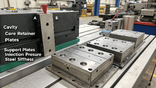
Mold plate thickness, particularly for the cavity and core retainer plates (A and B plates) and any support plates, must be sufficient to prevent bending under injection pressure and clamping force. Key factors influencing required thickness include cavity size/depth, expected injection pressure, steel stiffness, and the location/number of support pillars.

Ensuring the mold base plates are rigid enough is crucial for maintaining part quality and mold longevity. Deflection is the enemy here. - ### Resisting Injection Pressure: During injection, molten plastic pushes outward against the cavity and core surfaces with significant force (often thousands of PSI). This force is spread over the area of the cavity. Larger parts or parts molded at higher pressures generate more total force trying to push the mold halves apart or bend the plates. The plates holding the cavity and core inserts (A and B plates) need to be thick enough to resist this bending. The depth of the cavity or core also matters – a deep feature creates a longer unsupported span, increasing the risk of deflection. We sometimes use basic beam deflection calculations or FEA (Finite Element Analysis) on critical projects at CKMOLD to verify plate rigidity.
- ### Role of Support Plates & Pillars: The B-plate (core side) is usually supported from behind by a support plate and, critically, by support pillars (also called support posts or rails) located within the ejector housing. These pillars transfer the clamping force and the injection pressure pushing against the core directly to the machine’s moving platen. Their number, size, and strategic placement are vital to prevent the B-plate and the support plate from sagging in the middle. Insufficient support here is a common cause of mold deflection and flashing issues, especially in larger molds. The required thickness of the support plate itself depends on the span between these pillars.
- ### Cooling Channel Considerations: The network of cooling channels drilled through the mold plates must also be considered. Plates need to be thick enough to accommodate these channels (often 8-12mm diameter or more) without compromising the structural strength needed to resist deflection. Placing large channels too close to the surface or too close together in a thin plate can weaken it significantly.
- ### Standard Thicknesses & Adjustments: Standard mold bases (e.g., DME, Hasco) come with pre-defined standard plate thicknesses for each base size. These are generally engineered to be sufficient for typical applications. However, for parts with unusually large projected areas, deep features, or requiring very high injection pressures, it’s essential to verify if the standard thicknesses provide enough rigidity. Sometimes, specifying thicker-than-standard plates (which adds cost and weight) or adding more support pillars might be necessary. I recall one instance where sticking with a standard thickness on a large, thin-walled part resulted in subtle bowing, causing dimensional issues we had to chase – reinforcing the need for careful checking.
What are the Criteria for Selecting Mold Base Material?
Does the steel used for the main mold base plates need to be super hard like the cavity and core? Not usually. Using the wrong type of steel for the base can lead to unnecessary costs or, conversely, premature wear or lack of rigidity. Let’s clarify the material selection for the base itself.
Material selection for the mold base plates prioritizes structural integrity, stability, good machinability for adding components, and overall cost-effectiveness. Common choices include medium-carbon steels (like 1045 or S50C/S55C) for standard bases, offering a good balance of properties. Pre-hardened steels (like P20) are sometimes used for higher strength requirements.

While the cavity and core materials grab the spotlight due to their direct contact with plastic, the mold base material is the unsung hero providing the foundation. - ### Standard Base Materials (e.g., S50C/1045): For the majority of applications, standard medium-carbon steels like Japanese S50C/S55C or AISI 1045 are the workhorses for mold base plates (Top Clamping Plate, A-Plate, B-Plate, Support Plates, Ejector Housing). These materials offer good tensile strength and rigidity to support the mold components and withstand clamping forces. Crucially, they have excellent machinability, which is important because pockets for cavities, cores, leader pins, bushings, sprue bushings, locating rings, and holes for ejector pins, cooling lines, and assembly bolts need to be machined into them. They provide a cost-effective solution for the bulk of the mold structure.
- ### Pre-Hardened Steels (e.g., P20): Sometimes, a higher-grade steel like P20 (or similar materials like 1.2311, 1.2312) is used for the main A and B plates, or even the entire base. This might be chosen if:
- Higher overall rigidity or strength is needed, perhaps for a very large mold or high-precision application.
- Some simple forming features or runner channels are machined directly into the A or B plate instead of using separate inserts. P20 offers better wear resistance than S50C.
- A longer overall base lifespan is desired, providing better resistance to wear and tear from handling and operation.
Using P20 for the entire base increases the cost significantly compared to standard carbon steel bases.
- ### Hardness vs. Machinability Trade-off: Unlike cavity and core steels (H13, S136, etc.) that need high hardness (48+ HRC) for wear and polish, mold base plates typically don’t require extreme hardness. Their main job is structural support. Standard base steels are usually supplied around 18-22 HRC, while P20 is around 28-32 HRC. This lower hardness range makes them much easier and faster to machine, reducing the cost of manufacturing the mold base.
- ### Consistency and Quality: Regardless of the specific grade chosen, it’s vital to use high-quality steel from reputable suppliers. Companies specializing in standard mold bases (like DME, Hasco, LKM, or trusted partners CKMOLD works with) ensure consistent material properties, dimensional tolerances, and proper stress-relieving. Using cheap, low-quality steel for the base can lead to warping, cracking, or inconsistent performance, ultimately costing more in the long run. This reliability is crucial for designers like Jacky who depend on consistent manufacturing.
How Does Machine Size Influence Mold Base Selection?
Can you design a mold base in isolation without thinking about the injection molding machine? Absolutely not! Designing a fantastic mold that doesn’t fit or run properly in the intended press is a recipe for major problems and delays. Let’s link the base to the machine.
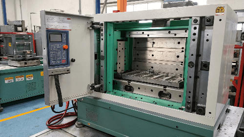
The specifications of the target injection molding machine directly constrain your mold base options. You must confirm the base fits the tie bar spacing and platen size, meets the machine’s mold height limits, and that the machine provides sufficient clamp tonnage and opening stroke for the mold and part.

The injection molding machine isn’t just a power source; it’s an integral part of the system that physically interacts with and limits the mold base design. - ### Tie Bar Spacing & Platen Dimensions: As mentioned when discussing size, the mold base’s overall width and height must be smaller than the distance between the machine’s tie bars (horizontal and vertical). Furthermore, the base must fit onto the machine’s platens (the large steel plates that clamp the mold shut). This includes having enough space not just for the base footprint but also for the physical clamps used to bolt the mold to the platen. Standard mold bases usually have recommended clamp slot positions. Always get the machine platen drawing if possible.
- ### Mold Height & Clamp Stroke: Every machine has a minimum and maximum mold height (or thickness) it can accommodate. Your chosen mold base assembly’s total height must fall within this range. The machine also has a maximum clamp stroke or opening distance. This stroke needs to be large enough to open the mold sufficiently to eject the part cleanly. Remember to account for the part height plus the ejector stroke plus any additional clearance needed, especially if robotic part removal is used. A complex mold with actions might require a larger opening than a simple open-and-shut mold.
- ### Clamp Tonnage Consideration: The machine’s clamp tonnage (the force holding the mold closed) must be sufficient to counteract the injection pressure pushing the mold open (calculated roughly as Injection Pressure x Part Projected Area). While this primarily dictates the minimum size of the machine needed, the mold base must be robust enough to handle these forces without excessive deflection and suitable for mounting on a machine of that tonnage class. You wouldn’t typically put a tiny mold base designed for a 50-ton press into a 500-ton press, even if it physically fits, as the machine parameters might be overkill.
- ### Early Communication is Key: The absolute best practice is to know the exact make and model of the injection molding machine(s) the mold will run in before finalizing the mold base design. For designers like Jacky, this means getting this information from the manufacturing department or the client’s molding facility early on. If the exact machine isn’t known, design the base for a common machine size within the expected range and clearly document the assumed specifications (tie bar spacing, platen layout, max/min height, stroke). Designing in a vacuum here is risky. I learned this the hard way once when a finished mold arrived at the client’s site only to find their standard clamp pattern was different from what we assumed – leading to urgent modifications and delays. Communication prevents this!
Conclusion
Choosing the right injection mold base isn’t just about picking a size. It involves carefully considering the part design, number of cavities, required mechanisms, material, intended machine, and budget. Getting these steps right lays the foundation for efficient, reliable, and cost-effective injection molding.
-
Exploring this topic will provide insights into how production volume influences material and design choices for mold bases. ↩
-
Exploring the impact of cavity and core dimensions on mold design can enhance your knowledge and improve your design accuracy. ↩
-
Learning about the runner system’s role in mold design can help you create more efficient and effective molds. ↩
-
Understanding various gating methods can help you choose the right mold design for your specific part requirements. ↩
-
Learning about these configurations can provide insights into advanced mold design techniques for complex parts. ↩
