
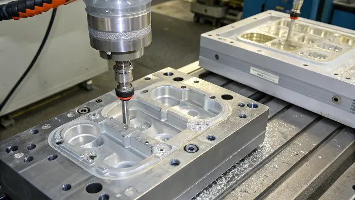
Quick answer: An injection mold is a coordinated production system. Its feed path delivers melt, cavity/core create shape, vents release gas, cooling removes heat, guidance and locks hold alignment, actions release undercuts, and ejection removes the part; failure at an interface often appears as a product defect elsewhere.
Feed the Cavity
The sprue, runner, hot runner and gate control pressure loss, shear, residence, balance, vestige and packing access. Gate position sets flow direction, weld lines and air movement. The feed system must match resin, cavities, color-change and maintenance needs.
Review the nozzle and sprue interface, cold-slug management, gate inserts and access for cleaning. In multi-cavity tools, small variations can create different part weights and dimensions.
Form and Support the Part
Cavity and core surfaces define nominal geometry, finish and many datums. Inserts create details and provide correction or wear options. Support plates and pillars resist cavity pressure; interlocks maintain alignment beyond guide pins.
Trace critical dimensions to the steel components that create them. Features crossing parting or moving actions accumulate fit and clearance variation. Steel strength, heat treatment and maintenance influence repeatability.
Release Air Through Vents
Melt displaces air and process gas toward end-of-fill regions, weld lines, ribs and pockets. Parting-line vents, inserts, ejector clearances or designed overflows provide escape routes. Vents must be deep enough to work and shallow enough to avoid flash for the actual material.
Make vents accessible for cleaning. Deposits can turn a previously stable cavity into burns or short shots, so maintenance belongs to vent design.
Engineering Scope
| Mold system | Primary job | Common interface |
|---|---|---|
| Feed | Deliver balanced, controlled melt | Machine nozzle, hot runner, gate and cavity |
| Form and align | Create geometry and resist pressure | Parting line, inserts, interlocks and support |
| Thermal/vent | Remove heat and displaced gas | Circuits around gates, cores, actions and end of fill |
| Release | Move undercuts and eject part | Draft, actions, pins, robot and mold protection |
Illustrative System Interaction
Illustrative engineering example—not a claimed CKMOLD customer result: A part develops a burn near a deep rib after several production hours. Raising pressure worsens it. Inspection finds the end-of-fill vent has accumulated deposit because it is difficult to access. The durable correction addresses vent service and cleaning frequency rather than treating the symptom as a machine-setting problem.
Remove Heat With Controlled Circuits
Cooling channels, baffles, bubblers, inserts and temperature-control equipment set surface temperature, cycle and shrinkage balance. Circuits should follow thermal load while preserving structural steel and access. Deep cores and actions are frequent hot spots.
Label supply and return, verify flow and plan water quality. Equal controller setpoints do not ensure equal cavity temperature when circuits differ in length or restriction.
Move Undercuts Reliably
Slides, lifters, hydraulic cores, unscrewing and collapsible systems release geometry that cannot move in the main opening direction. Each needs stroke, guidance, support, lock, lubrication, sensing and a safe sequence.
Actions affect parting lines, cooling, tolerance, wear and cycle. Use them where product function justifies the lifecycle burden and provide service access and spares for critical wear components.
Eject and Protect the Mold
Pins, sleeves, strippers and air assist distribute release force after the part has enough stiffness. Draft, polish, core grip and texture control the required force. Poor support can mark or deform the part.
Coordinate mold opening, ejector, actions and robot. Sensors and low-force mold protection help prevent clamping on a part or action. Validate warm-part handling and return positions through repeated cycles.
Engineering Record Checklist
- Map nozzle, runner, hot runner, gates and packing path.
- Trace CTQs to cavity, core, inserts, parting and actions.
- Review structural support, guidance, interlocks and wear.
- Locate and service vents at real end-of-fill regions.
- Design cooling for thermal load, flow verification and maintenance.
- Define action stroke, lock, lubrication, sensing and sequence.
- Distribute ejection force around draft, grip and hot stiffness.
- Validate robot, mold protection and system interaction in trials.
Related Engineering Resources
Engineering Questions
What are the main systems in an injection mold?
Feed, forming and support, guidance, venting, cooling, actions and ejection work together with the machine and controls.
Why is venting part of mold design?
The incoming melt must displace cavity air and gas; blocked or inadequate vents can cause burns, short shots and deposits.
Do guide pins hold cavity pressure alignment?
They guide closing, while interlocks, parting fit and structural support may be needed to resist production loads accurately.
Why can a mold defect appear after stable production?
Wear, deposits, blocked circuits, action clearance, lubrication or material change can alter one system and create a new part symptom.
Apply the Injection Mold Systems Map review to your released design. Share the function, exact resin, annual volume, CTQs, cosmetic limits and launch timing through the CKMOLD project form. If CAD is relevant, send it directly to jerry@ckmold.com; the form does not require an upload.