
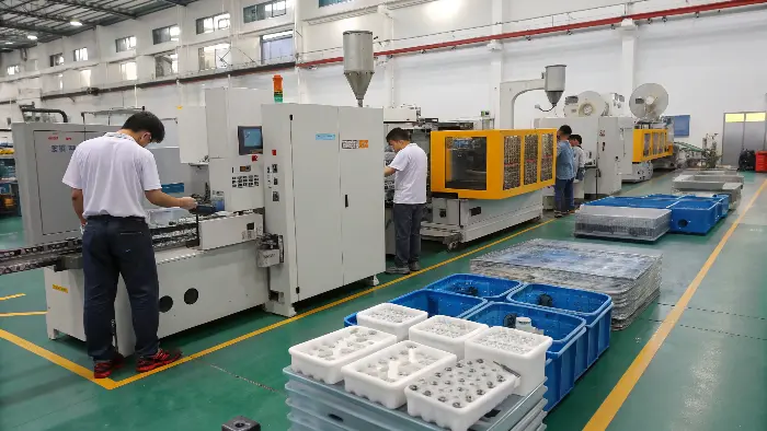
Are your plastic parts too heavy, costly, or time-consuming to produce? Traditional molding might be holding you back. Imagine lighter, quicker, and more efficient manufacturing. Thin wall injection molding gives you the tools to make it a reality, transforming your production process.
Thin-wall injection molding is a production strategy for reducing part mass or creating compact packaging, housings and components while maintaining function. The challenge is not thickness alone; flow length, gate, resin viscosity, injection rate, venting, mold temperature, cooling and ejection combine to determine whether the part fills and remains stable.
Related CKMOLD resources: DFM analysis, rapid tooling, production injection molding.
Thin wall injection molding is a unique process employed for the production of plastic parts of very thin wall thicknesses of less than 1mm. It needs high precision, high shot speed, and special equipment and materials. It enables large material savings, reduced cycle time, and production of light high-performance parts, and hence is adaptable to the requirements of present manufacturing demand.

Thin-wall design can reduce mass and shorten cooling, but only when stiffness, impact, appearance, assembly and yield remain acceptable. The business case should use accepted-part cost and a demonstrated process window rather than thickness reduction alone.
Define Thin Wall by Flow Demand and Required Function
Thin wall is a process-demand description, not a universal “below 1 mm” rule. Thickness must be considered with flow length, grade viscosity and crystallization, gate, surface, ribs/bosses, projected area, required fill time and machine response. A 1.2 mm short-flow PP lid may be straightforward while a thicker long-flow reinforced housing may be more demanding.
Write the functional limits first: stiffness, impact, flatness, assembly, appearance, barrier or electrical performance. Then evaluate whether reduced wall mass is still moldable and testable. A lower nominal part weight is not a saving if it creates a narrow process window or higher reject rate.

Design Decisions That Control a Thin-Wall Process
- Wall path: keep transitions deliberate; use ribs or shape for stiffness only after sink, flow and ejection review.
- Gate/feed: minimize harmful pressure loss and orient flow/welds away from critical areas.
- Venting: provide serviceable gas escape at actual end-of-fill regions.
- Mold support: control parting deflection, cavity balance and action/shutoff load.
- Cooling/ejection: release the warm, flexible part without distortion or marks.
Draft, rib ratio and radius must come from the exact grade, draw depth, texture and structural requirement. Fixed 1–2° or 50–60% rules should not be copied across materials and geometries.
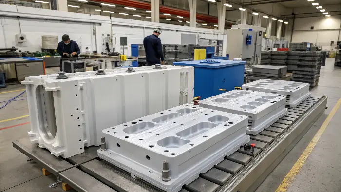

Select an Exact Grade, Not a Polymer Family
High-flow PP, PC, ABS, PA and other grades can be candidates, but flow rating alone does not establish impact, stiffness, appearance, shrinkage, compliance or weld-line performance. Compare supplier data at the relevant test condition and confirm drying, melt/mold range, residence and shear limits.
SABIC’s LEXAN library shows why grade identity matters: PC grades are listed with different flow, reinforcement, UV, flame and release attributes. Apply the same grade-level discipline to every material family; the PC molding guide covers that family in context.
Mold representative parts and test flatness, weight, dimensions, drop/impact, assembly and aging across the intended process window. Do not select solely from MFR/MVR because those tests do not reproduce the complete cavity flow. If lightweighting is also a waste objective, compare accepted yield and runner/startup loss using the mold waste-reduction framework.
Prove Machine and Tool Capability Before Release
Thin-wall parts may require high injection rate, adequate pressure reserve, precise transfer, stable recovery, sufficient clamp distribution, rapid venting and stiff tooling. Tonnage alone is not a capability test. Request the proposed screw, maximum usable injection rate/pressure, shot range, response, platen/tie-bar fit and cooling capacity.
At trial, record fill time, pressure, transfer, cushion, part weight, cavity balance, flash, dimensions, flatness and ejection at more than one condition. A stable window—not the fastest single cycle—supports production approval. Define the evidence through mold testing and validation.
Define Thin Wall by Flow and Function
A short thin wall in a compact part may be easy to fill, while a long thin panel may require high speed and pressure. Ribs, bosses, corners, texture, inserts and tolerance add difficulty. The design review should define the functional load and the minimum wall that can survive molding and use.
Gate and Venting Are the First Tool Decisions
The gate must deliver material before the wall freezes, and its direction should avoid free jetting or a visible defect. Vents at the end of fill and around ribs or inserts allow air to leave. A restrictive runner or small gate can consume the available pressure before the part is full.
Machine Response Must Match the Fill Time
Thin walls may require rapid screw acceleration, high injection rate, pressure reserve and accurate speed profiling. Shot size, check-ring response, nozzle alignment and controller resolution influence the first moments of fill more than a nominal tonnage number.
Mold Stiffness and Cooling Protect the Shape
High pressure can open a weak parting line or move an insert. Cooling circuits must remove heat without creating directional shrinkage or a long cycle. Ejection should support the part while it is still warm, and handling should not bend it before inspection.
Validate With Weight, Flatness and Use Tests
Short shots, cavity weights, flatness, critical dimensions, appearance, impact and assembly provide stronger evidence than a complete-looking sample. Measure after a defined time and condition because thin parts can continue to relax after ejection.
Thin-Wall Injection Molding: Buyer Review Checklist
- Define flow length, wall, ribs, corners, inserts, surface and functional load together.
- Review gate, runner, venting, cold slug and fill direction before tooling.
- Match machine rate, pressure, shot reserve, check-ring response and control resolution.
- Design mold stiffness, cooling, draft, ejection and handling for the warm part.
- Validate short shots, weight, flatness, dimensions, appearance and end-use function.
FAQ
What is the main challenge in thin-wall molding?
The melt can freeze quickly while pressure, speed, venting and cooling must remain controlled across a long or detailed flow path.
Does thin-wall molding generally reduce cost?
It may reduce material and cycle, but high-speed machines, tooling, validation and scrap risk can change the total economics.
Conclusion
Thin wall injection molding offers incredible benefits for modern manufacturing, from significant cost savings and faster production cycles to enhanced product design and performance. While it presents unique challenges, understanding the core principles of part design, material selection, tooling, and process control allows us to overcome them effectively. This leads to innovative, efficient, and high-quality production of lightweight components.