It’s frustrating for a product designer when a great design fails on the production line because of overlooked molding principles. This can lead to budget overruns, missed deadlines, and a flawed final product. Mastering the basics of injection mold design is the essential first step to ensure your vision becomes a reality, smoothly and efficiently.
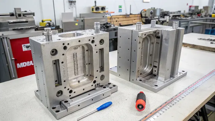
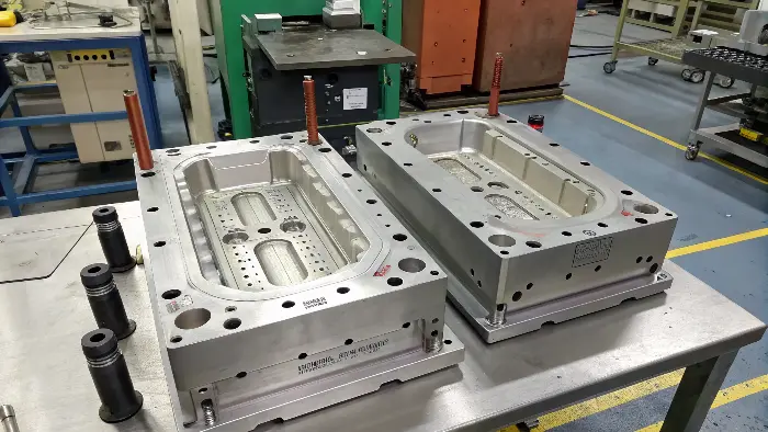
Injection mold design is the process of creating a specialized tool, the mold, that shapes molten plastic into a finished part. At its core, a mold consists of two halves: a cavity side (A-side) and a core side (B-side). When closed, they form a hollow space matching the part’s geometry. Hot, liquid plastic is then forced into this cavity under immense pressure. The design must meticulously account for how the plastic flows, cools, and shrinks, and how the final part will be safely ejected.

Understanding this concept is just the beginning. I’ve seen many talented designers like Jacky create beautiful products that were a nightmare to manufacture. To truly excel and avoid these common pitfalls, you need to go deeper into the core principles and components. This knowledge is the bridge between a digital model and a successful physical product. Let’s break down the essentials that every designer and engineer must master.
What are the basics of injection molding?
You have a solid product design, but the manufacturing process of injection molding feels like a complete black box. This uncertainty can make it incredibly difficult to design parts that are optimized for production. It often leads to frustrating back-and-forth communication with manufacturers and unexpected, costly problems on the factory floor. Let’s pull back the curtain and clarify the fundamental steps of the injection molding cycle.
Injection molding is a manufacturing process used to produce parts by injecting molten material into a mold. The cycle begins by clamping the two halves of the mold together with massive force. Next, molten plastic is injected into the mold’s cavity until it’s completely full. The plastic is then held under pressure while it cools and solidifies, perfectly taking the shape of the cavity. Finally, the mold opens, and the finished part is pushed out. This entire cycle repeats rapidly to produce identical parts with high precision.

To really grasp mold design, you first have to understand the machine and the process it enables. I remember my early days on the factory floor, watching these massive machines run. The power was incredible, but it was the precision of the cycle that truly fascinated me. Every single step has to be perfectly timed and controlled.
Radii – Why They are Necessary
While not always required, radii (angled internal and external corners) are strongly advisable in injection molding for a number of practical reasons.
First, radiused corners ensure improved material flow. Similar to water in a river, water avoids sharp turns. Similarly, molten plastic also favors smooth, gradual routes. Sharp 90-degree corners introduce resistance and retard the flow, which can result in incomplete fills or structural weaknesses in the part. Rounded corners guide the resin smoothly through the mold, providing even fill and enhanced structural integrity.
Secondly, radiusing will strengthen and harden the part. Sharp internal edges will function as a stress concentrator, which under tension has a tendency to crack. A simple radius will distribute the stress evenly and strengthen the part over time.
Last, ejection of the part is easier with radiused corners. Rounded edges will not catch on the mold when ejecting as readily, leaving less opportunity for warping or breaking the part. This allows for a faster, smoother production cycle.
The Injection Molding Cycle: A Step-by-Step Breakdown
The process is a finely tuned dance of pressure, temperature, and time. Let’s look at each stage in more detail.
| Stage | Description | My Insights |
|---|---|---|
| 1. Clamping | The two halves of the mold (core and cavity) are pressed together by a powerful hydraulic or electric clamping unit. | The force here is immense, often hundreds or thousands of tons. It has to be strong enough to hold the mold shut against the intense pressure of the injected plastic. If the clamp fails, you get "flash," where plastic seeps out of the parting line, creating a mess and a defective part. |
| 2. Injection | Plastic pellets are fed from a hopper into a heated barrel, where a reciprocating screw melts and mixes them. The screw then pushes forward, injecting the molten plastic into the mold cavity. | This is the heart of the process. Controlling the injection speed and pressure is critical. Too slow, and the plastic might cool before filling the mold (a "short shot"). Too fast, and you can get other defects. It’s a delicate balance that we fine-tune for every project. |
| 3. Dwelling & Cooling | After the cavity is filled, pressure is maintained for a short period (dwelling) to pack out the part and compensate for shrinkage. Then, the part is left to cool and solidify. | Cooling is often the longest part of the cycle, accounting for up to 80% of the total time. An efficient cooling channel design inside the mold is crucial for reducing cycle time and preventing defects like warping. This is where good mold design really pays off. |
| 4. Ejection | The clamping unit opens the mold. An ejection system, usually consisting of pins or plates, pushes the solidified part out of the core side of the mold. | For the part to come out cleanly, the design must include draft angles (slight tapers on the walls). I’ve seen projects delayed for weeks because a designer forgot this simple rule, causing parts to get stuck and damaged during ejection. |
Understanding this cycle is the foundation. Every decision in mold design is made to make this process as smooth, fast, and reliable as possible.
What is injection mold design?
You understand the molding process, but what exactly goes into designing the tool that makes it all happen? It’s a common blind spot. Without this knowledge, your product designs might be physically impossible or incredibly expensive to manufacture. This can lead to major project setbacks, budget revisions, and a lot of wasted time. Understanding injection mold design is about translating a 3D product model into a functional, durable, and efficient manufacturing tool.
Injection mold design is the detailed engineering of the tool used in injection molding. It involves creating the two primary halves—the cavity (often called the A-side) and the core (the B-side)—which together form the negative space of the final part. The design also incorporates several critical systems: the runner system to guide the molten plastic, the cooling system to manage temperature and solidify the part, and the ejection system to safely remove it. A successful design ensures high part quality, minimizes production time, and maximizes the mold’s operational life.

When I started my own company, I moved from just operating the machines to being responsible for the entire process, from design to delivery. This is where I learned that the mold is not just a simple block of steel. It’s a complex machine in its own right. Every component has a purpose, and they all must work together in perfect harmony. A well-designed mold is a work of art that can produce millions of perfect parts. A poorly designed one is a constant source of problems.
Single-Cavity vs. Multi-Cavity vs. Family Injection Molds
Single-Cavity, Multi-Cavity, and Family Injection Molds
Injection molds are generally classified as three types:
- Single-cavity molds
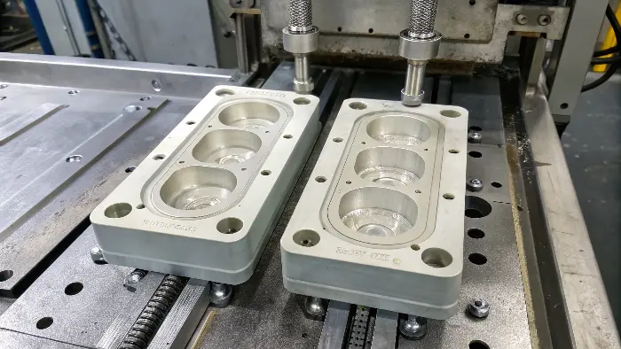
- Multi-cavity molds
- family Injection molds
Single-Cavity Injection Molds
Single-cavity injection molds consist of a single cavity and can be employed to make one product at a single instance. Single-cavity molds are an efficient, cost-effective way of making low-order quantity production processes or big or intricate parts. Single-cavity molds enable operators to give more attention to each single product to prevent air bubbles, unfilled areas in the mold, or other probable defects. Single-cavity molds are also less expensive compared to equivalent multi-cavity injection molds.
Multi-Cavity Injection Molds
Multi-cavity molds consist of multiple identical cavities. They enable manufacturers to fill all of the cavities simultaneously with molten plastic and make multiple products at once. As a result, they offer faster lead times for product lots, which improves the efficiency of production, reduces delays, and saves rush or volume-priced order money.
Family Injection Molds
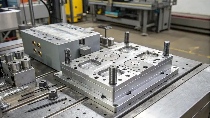
Family injection molds are similar to multi-cavity molds because they both have numerous hollows. Rather than numerous hollows all of the same size, each hollow is of a different size. Manufacturers are able to use these molds to create prototypes or different products that are placed into one variety pack.
This mold is useful in the production of different products which are made of the same elastomeric material. The hollows need to be ideally placed and sized, however; if the family mold is not balanced, the fluid will not be injected evenly and will result in manufacturing defects.
Core Components of an Injection Mold
Let’s break down the anatomy of a typical mold. While designs vary in complexity, they all share these fundamental components.
| Component | Function | Why It Matters for a Designer |
|---|---|---|
| Mold Base | The steel frame or foundation that holds all the other components together in a precise alignment. | This is the skeleton of the mold. While you might not design the base itself, your part’s size and complexity will determine the size and type of base required, which impacts the overall cost. |
| Cavity (A-Side) | The stationary half of the mold that usually forms the exterior, cosmetic surface of the part. It’s attached to the stationary platen of the molding machine. | This is often called the "show surface." The finish on the cavity steel (e.g., high polish, textured) directly translates to the finish on your product. The parting line is defined on this side. |
| Core (B-Side) | The moving half of the mold that usually forms the interior, non-cosmetic geometry of the part. It contains the ejection system. | The core creates the internal features. Because the plastic shrinks onto the core as it cools, the ejection system is housed here to push the part off. This is why draft angles are so critical on core-side features. |
| Runner System | The network of channels that guides molten plastic from the molding machine’s nozzle to the part cavity. It consists of the sprue, runners, and gates. | The design of this system affects how the part fills, where weld lines appear, and how much material is wasted. The gate location is especially important as it can impact the part’s final appearance and strength. |
| Cooling System | A network of channels drilled through the mold plates where a fluid (usually water) circulates to control the mold’s temperature. | This is the secret to fast cycle times and dimensionally stable parts. Poor cooling leads to long cycles, warpage, and sink marks. As a designer, uniform wall thickness in your part makes the cooling process much more effective. |
| Ejection System | The mechanism that pushes the finished part out of the mold after it has cooled. It’s typically a system of pins, sleeves, and plates. | Your design must allow for ejector pins to push against the part without causing damage. This means providing flat, robust surfaces for the pins to act on, preferably in non-cosmetic areas. |
Each of these systems must be designed in concert with the others. A change in the gate location might require a change in the cooling layout, which could affect where ejector pins can be placed. It’s a complex puzzle that requires a holistic approach.
What are the fundamentals of mould design?
You know the process and the parts of a mold, but what are the core principles that separate a successful mold from one that fails? Ignoring these fundamentals is a direct path to common molding defects like ugly sink marks, warped parts, or incomplete filling. These issues waste material, drive up costs, and can even ruin a product launch. Mastering a few key design fundamentals is the secret to creating robust molds that produce perfect parts, every single time.
The fundamentals of mold design are all about ensuring a part can be manufactured efficiently and without defects. The most critical principles include incorporating a draft angle for easy part release, maintaining uniform wall thickness to prevent sink marks and warpage, and designing an effective gating and runner system for optimal plastic flow. Furthermore, accurately planning for material shrinkage and integrating a robust cooling system are essential for achieving dimensional accuracy and minimizing cycle time.

I’ve had to troubleshoot hundreds of molds over the years, and I can tell you that 90% of the problems trace back to a violation of one of these fundamental principles. A client once brought me a design for a simple housing. It looked great on screen, but it had perfectly vertical walls and a thick rib right next to a thin wall. They had already paid for a mold to be made elsewhere, and it was a disaster. The parts were getting stuck, and the thick rib caused a huge sink mark on the cosmetic face. We had to re-design the part and re-build the mold, a costly lesson in the importance of getting the fundamentals right from the start.
Key Principles for Successful Mold Design
These aren’t just suggestions; they are the rules of the road for injection molding. If you are a product designer like Jacky, embedding these into your workflow will save you countless headaches.
| Principle | Description | Practical Application & Impact |
|---|---|---|
| Draft Angle | A slight taper applied to the vertical walls of a part in the direction of mold pull. | Why: As plastic cools, it shrinks and grips onto the mold core. Without a draft angle, the friction is too high, and the part can be damaged or get stuck during ejection. Application: A standard rule of thumb is to apply at least 1-2 degrees of draft per side. Textured surfaces require even more. Always add draft; never assume it’s optional. |
| Uniform Wall Thickness | Designing the part so that all its walls have the same thickness wherever possible. | Why: Thick sections cool much slower than thin sections. This differential cooling creates internal stresses that cause the part to warp or twist. It also causes ugly depressions called sink marks on the surface opposite the thick section. Application: Aim for a consistent thickness. If you need a rib for strength, make its base no more than 50-60% of the main wall thickness to avoid sink marks. |
| Material Shrinkage | The reduction in size that all plastics undergo as they cool from a molten state to a solid state. | Why: The mold cavity must be machined larger than the final desired part dimensions to compensate for this shrinkage. Application: Every plastic has a different shrinkage rate (e.g., ABS is ~0.5%, while Polypropylene can be 1.5-2.0%). The mold designer must know the exact material you plan to use to calculate this compensation accurately. A wrong calculation means an out-of-spec part. |
| Parting Line | The line on the part where the two halves of the mold (core and cavity) meet. | Why: The location of the parting line affects the mold’s complexity, cost, and the final appearance of the part. A visible line will be present on the final product. Application: Try to place the parting line along a sharp, natural edge of the product to hide it. A simple, flat parting line is always cheaper and more reliable than a complex, stepped one. |
| Gating & Venting | Gates are the small openings where plastic enters the part cavity. Vents are tiny channels that allow the air inside the cavity to escape as plastic flows in. | Why: Poor gate location can cause cosmetic flaws or weak points (weld lines). Inadequate venting traps air, which can cause incomplete parts ("short shots") or burn marks from compressed, superheated air. Application: Work with your molder to determine the best gate location. It should be in a non-cosmetic area and placed to promote a balanced fill pattern. |
By designing your parts with these principles in mind from day one, you are no longer just creating a shape. You are engineering a product for successful manufacturing.
Conclusion
In the end, mastering injection mold design comes down to a few key areas. It starts with a solid grasp of the molding process itself, followed by knowing the core components of the mold. Most importantly, it’s about applying the fundamental design principles like draft, uniform walls, and shrinkage. Focusing on these details is how you create efficient, reliable molds that turn great ideas into high-quality, manufacturable products. This foundation is your key to success.
