Are you struggling with inconsistent plastic parts that slow down your assembly line and hurt your brand’s reputation? These production hiccups eat into your profits, delay your projects, and create constant stress. At CKMOLD, we believe the solution starts before a single piece of steel is cut. Our advanced tool design is engineered from the ground up to prevent these problems, ensuring your success.
We engineer molds for maximum efficiency and quality by focusing on a holistic design process. This includes detailed Design for Manufacturability (DFM) analysis, precise material selection, advanced cooling system design, and rigorous simulation testing. By optimizing every element, from the gate location to the steel used, we ensure the mold produces consistent, high-quality parts with the shortest possible cycle times. This proactive approach minimizes defects and maximizes your return on investment from day one.
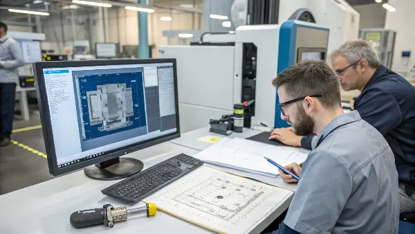
Achieving this level of precision isn’t magic; it’s the result of a systematic engineering process that we have perfected over many years. It’s about building quality into the tool itself, not just inspecting it at the end. For business owners like you, understanding this process is key to choosing the right manufacturing partner.
Let’s dive deeper into the core principles we use at CKMOLD to turn your concepts into high-quality, efficiently produced parts. We’ll start with the foundation of every successful project.
What is the concept of Mould design?
Do you view a mold as just a shaped block of steel? This common misconception can be costly. A poor mold design leads to endless headaches, including part defects, slow production speeds, and frequent tool repairs, all of which drain your budget and delay your timelines. Understanding the core concept of mold design reveals it’s a detailed engineering blueprint for manufacturing success.
Mold design is the comprehensive engineering process of creating a detailed blueprint for a tool that shapes plastic parts through injection molding. It’s much more than just the cavity’s shape. It involves selecting the right materials, designing the feed system (sprue, runners, gates), planning the cooling channels, creating an ejection mechanism, and ensuring the mold’s structural integrity. A great design perfectly balances part quality, production speed, and tool longevity to meet your specific project goals.
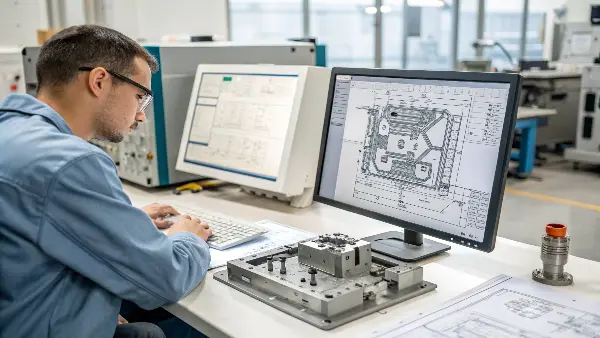
When I first started in this industry, I saw firsthand how a well-designed mold could run flawlessly for millions of cycles, while a poorly designed one was a constant source of problems. Mold design is truly where the foundation for a successful product is laid. It’s an upfront investment of time and expertise that pays for itself many times over during the life of the tool. It’s a mix of science and art, requiring deep knowledge of material properties, fluid dynamics, and thermodynamics. Let’s break down some of the most critical components.
Core and Cavity: The Heart of the Mold
The core and cavity are the two halves of the mold that come together to form the shape of your part. The "cavity" is the fixed half and typically forms the exterior, or "A-side," of the component—the side you usually see. The "core" is the moving half and forms the interior, or "B-side." The precision here is everything. We engineer these surfaces with exact tolerances, specific surface finishes, and calculated draft angles (slight tapers) to ensure the part not only looks perfect but also releases from the mold easily without damage.
The Feed System: Guiding the Plastic
The feed system is the network of channels that guides the molten plastic from the injection molding machine’s nozzle into the cavity. It consists of:
- Sprue: The main channel where plastic first enters the mold.
- Runners: Smaller channels that branch off the sprue to lead plastic toward the part cavities.
- Gates: The final, narrow opening through which the plastic enters the cavity. The type and location of the gate are critical for controlling how the part fills.
| Gate Type | Description | Best For |
|---|---|---|
| Edge Gate | Located on the parting line of the mold. Simple and cost-effective. | Flat, simple parts. |
| Submarine Gate | Ejects automatically, cutting the runner from the part. | High-volume production, small parts. |
| Hot Tip Gate | Part of a hot runner system, injects plastic directly into the part. | Eliminating runner waste, large parts. |
How does mould cooling affect the quality and efficiency of the injection molding process?
Are your production cycle times longer than quoted, or are you seeing frustrating defects like warped parts? This inefficiency drives up your cost per part and creates a high scrap rate, directly hitting your bottom line. The solution often lies in a frequently overlooked but critical element of the mold design: the cooling system.
Mold cooling is crucial because it controls the rate at which the molten plastic solidifies, directly impacting both quality and efficiency. Proper cooling ensures a uniform temperature across the part, which minimizes defects like warpage, sink marks, and internal stresses. It also dictates the cycle time; faster, more efficient cooling allows for quicker part ejection, significantly boosting production output. A well-designed cooling system means better parts, made faster.
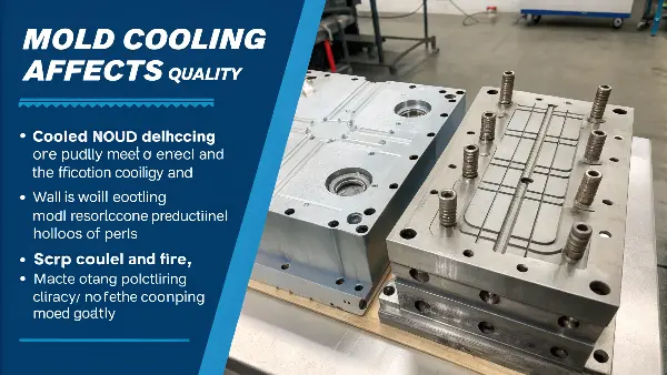
In any injection molding cycle, the cooling phase is by far the longest, often taking up 70-80% of the total time. Shaving just a few seconds off the cooling time can lead to a massive increase in output over a large production run. I remember one project where a client was struggling with long cycles and warped parts from their previous supplier. By redesigning the mold with an optimized cooling layout, we cut their cycle time by 30% and virtually eliminated the warping issue. This is the power of expert cooling design.
The Direct Link Between Cooling and Cycle Time
Think of it this way: you can’t eject a part until it’s solid enough to hold its shape. The faster you can uniformly remove heat from the molten plastic, the faster it solidifies, and the faster you can start the next cycle. Inefficient cooling, with hot spots in the mold, creates a bottleneck for your entire operation. We use Moldflow simulation software to analyze heat distribution and strategically place cooling lines to ensure even and rapid temperature reduction, maximizing your production efficiency.
Common Defects from Poor Cooling
Uneven cooling is a primary cause of quality issues. When one area of a part cools much faster than another, it creates internal stresses that lead to visible defects.
- Warpage: The part twists or bends as it cools due to uneven shrinkage.
- Sink Marks: Small depressions or craters on the surface, typically over thick sections that take longer to cool.
- Dimensional Instability: The final part dimensions are inconsistent and don’t match the design specifications.
Advanced Cooling: Conformal Cooling
For complex parts with intricate geometries, traditional straight-drilled cooling lines can’t always provide uniform cooling. In these cases, we use a more advanced technique called conformal cooling. Using 3D printing technology, we can create cooling channels that follow the exact contours of the part’s surface. This allows the cooling fluid to flow much closer to difficult-to-reach areas, providing incredibly uniform temperature control.
| Cooling Method | Uniformity | Cycle Time | Best For |
|---|---|---|---|
| Conventional | Good for simple shapes | Standard | Cost-effective, simple parts |
| Conformal | Excellent | Reduced by 30-50% | Complex geometries, high-performance parts |
How do you control quality in manufacturing?
Have you ever approved a perfect "golden sample," only to find that the quality of the mass-produced parts is inconsistent? This unpredictability creates chaos in your supply chain and can lead to customer complaints, product returns, or even damaging recalls. Consistent quality is never an accident; it is the direct result of a robust quality control system that is woven into every single stage of the manufacturing process.
We control quality in manufacturing through a multi-layered approach that begins long before the first part is ever produced. This system involves three key phases: proactive design (DFM), in-process monitoring, and final inspection. Proactive design prevents issues from ever occurring. In-process controls catch any deviations as they happen using real-time data and trained operator checks. Finally, a rigorous final inspection verifies that every batch meets all required specifications before it leaves our facility.
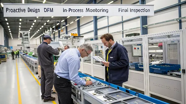
For us at CKMOLD, quality control is a philosophy, not a department. It’s about building a culture where every team member is responsible for the quality of their work. We learned early on that it is far more effective and less expensive to prevent a problem than it is to find it and fix it later. This mindset shift is what separates reliable suppliers from the rest. It’s about being proactive, not reactive. For a business owner like you, this means fewer surprises and a supply chain you can truly depend on.
Quality as a Proactive, Not Reactive, Process
The most effective quality control happens at the very beginning: the design stage. We run a comprehensive Design for Manufacturability (DFM) analysis on every part. This process identifies potential problem areas—like walls that are too thin, sharp corners that could cause stress, or sections that might be difficult to fill—and we solve them on the computer before they become expensive real-world problems. We also use advanced Moldflow simulation software to predict how the plastic will behave inside the mold, allowing us to optimize the design for a smooth, defect-free molding process.
The Human Element and Documentation
Technology is a powerful tool, but it’s our people who truly ensure quality. We invest heavily in training our operators, engineers, and inspectors. They are taught not just how to do their jobs, but why their attention to detail is so critical to our clients’ success. We empower them to stop a production line if they see something that isn’t right. This is supported by meticulous documentation. Every step, from the raw material certification to the final inspection report, is recorded and traceable. This gives you full transparency and is essential for industries with strict regulatory requirements.
What are the four methods used in quality control in production?
You often hear the term "quality control," but you might not be sure what concrete actions this involves on the factory floor. Without a clear understanding of the methods, you can’t properly evaluate a supplier’s ability to deliver the consistent quality your business depends on, leaving you vulnerable to costly errors. Let’s break down the four essential, practical methods we use to guarantee part quality during production.
The four primary methods for production quality control are Process Control, Product Inspection, Corrective and Preventive Actions (CAPA), and Supplier Quality Management. Process Control involves monitoring key manufacturing parameters in real-time. Product Inspection systematically checks parts against specifications. CAPA addresses the root cause of any identified issues to prevent them from happening again. Finally, Supplier Quality Management ensures the raw materials we use meet our own high standards from the start.
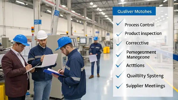
These four methods work together as a closed-loop system. It’s not enough to just inspect parts at the end; that only tells you that you’ve already made bad parts. A truly robust system uses process data to keep production stable, inspection to verify the output, corrective actions to fix any deviations, and supplier management to ensure you’re starting with good ingredients. This comprehensive approach is how we build reliability and trust with our clients. It transforms quality from a goal into a repeatable, measurable process.
Diving into the Four Methods
We integrate these four pillars into our daily operations to create a strong quality framework.
- Method 1: Process Control: We use Statistical Process Control (SPC) to monitor critical molding parameters like injection pressure, melt temperature, and cooling time. By tracking this data on control charts, we can see subtle shifts in the process and make adjustments before they lead to out-of-spec parts. It’s about controlling the process to control the outcome.
- Method 2: Product Inspection: This is what most people think of as quality control. It includes a First Article Inspection (FAI) for every new tool, where we measure every single dimension on the drawing. During production, we conduct regular in-process checks at the machine and a final outgoing inspection on a statistically significant sample of the finished batch. We use a range of tools, from simple calipers to advanced Coordinate Measuring Machines (CMMs).
- Method 3: Corrective and Preventive Action (CAPA): When a problem is found, we don’t just fix the part; we find the root cause. We use simple but effective techniques like the "5 Whys" to dig deep and understand what truly went wrong. Once the root cause is identified, we implement a corrective action to fix it and a preventive action to ensure it can never happen again.
- Method 4: Supplier Quality Management: The best process in the world can’t make a good part from bad material. We maintain a list of approved suppliers and require material certifications for every batch of resin. We verify that the material is the correct grade, color, and meets all performance specifications before it ever enters our machines.
| Method | Purpose | CKMOLD’s Application Example |
|---|---|---|
| Process Control | Prevent defects by monitoring the process. | Using SPC charts to track molding machine pressure. |
| Product Inspection | Find defects by checking the parts. | Performing a full dimensional FAI report for a new mold. |
| CAPA | Eliminate the cause of defects. | Using a "5 Whys" analysis to fix a recurring flash issue. |
| Supplier Management | Ensure input quality. | Requiring and verifying material certificates for every resin batch. |
How is the quality of molded parts controlled?
Even with a perfect mold design and a controlled manufacturing process, how do you truly know that the final parts you receive are perfect? A single bad batch of components that slips through can halt your entire assembly line, costing you thousands of dollars in downtime and potentially causing you to miss critical shipping deadlines. We control the quality of the final molded parts through a rigorous, multi-stage verification process that leaves nothing to chance.
The quality of molded parts is controlled by a combination of material verification, process parameter stability, and dimensional/visual inspection. First, we certify that the correct plastic resin is used. Second, we lock in and monitor critical molding parameters like temperature, pressure, and time. Finally, parts are systematically inspected using advanced equipment (like CMMs) for dimensional accuracy and visually checked for cosmetic defects like flash, sink marks, or short shots. This ensures every part conforms to the approved design.
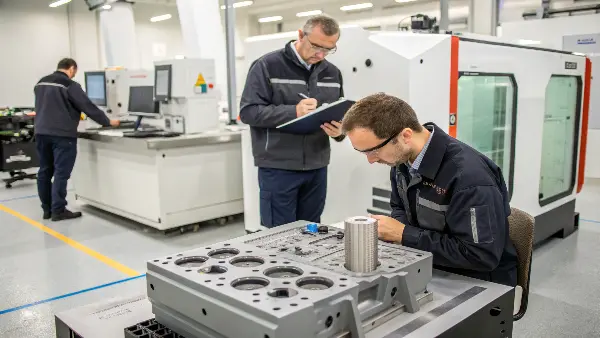
This final check is the gatekeeper that protects your business. It’s the last line of defense, and we take it extremely seriously. For a business owner like you, this process provides the ultimate peace of mind. It’s our guarantee that the parts you receive in your shipment are the same high quality as the "golden sample" you approved. Let’s walk through the specific steps we take to ensure this happens every single time.
Step 1: Upfront Material and Process Verification
Before we start a full production run, quality control begins. First, we confirm the raw material. We check the packaging, labels, and the material Certificate of Conformance (CoC) to ensure it’s the exact grade and brand specified in your project requirements. Next, we establish a stable molding process. Our engineers "dial in" the optimal machine settings—temperatures, pressures, speeds, and times—and save these parameters. This "master process" is then locked for the production run to ensure every part is made under identical conditions.
Step 2: First Article Inspection (FAI)
The First Article Inspection is one of the most critical steps. Once the process is stable, we produce a small number of initial parts. We then take one or more of these parts and perform a comprehensive inspection, measuring every single dimension noted on your 2D engineering drawing. The results are documented in a detailed FAI report that compares the actual measurements to the required specifications, including tolerances. We don’t proceed to mass production until you have reviewed and approved this report. This step confirms that the tool is capable of producing parts that meet your design intent.
Step 3: In-Process (IPQC) and Final (FQC) Checks
Once mass production begins, quality control is continuous.
- In-Process Quality Control (IPQC): Our machine operators and roving QC inspectors take sample parts at regular, predetermined intervals (e.g., every hour). They check critical dimensions and perform a quick visual inspection to ensure the process remains stable.
- Final Quality Control (FQC): After the entire batch is produced, a final inspection is performed before packaging. A quality inspector takes a statistically significant random sample from the batch (based on AQL standards) and performs a more thorough check for both dimensional accuracy and cosmetic appearance. This is the final approval before the parts are cleared for shipment to you.
| Inspection Stage | What We Check For |
|---|---|
| Material Verification | Correct resin type, grade, color, and valid certificate. |
| First Article (FAI) | All dimensions on the drawing, surface finish, color match. |
| In-Process (IPQC) | Critical dimensions, part weight, visual defects (flash, sink marks). |
| Final (FQC) | AQL sample check of dimensions, cosmetics, and packaging. |
Conclusion
In the end, achieving maximum efficiency and superior part quality is not a matter of luck. It is the direct result of expert tool design, a deep understanding of the molding process, and an unwavering commitment to quality at every single step. From the initial DFM analysis to the final inspection, every action we take is designed to build success directly into your project, ensuring you receive reliable, high-quality parts on time, every time.
