Have you ever modeled what seems to be a perfect plastic part, then when you put it into molding you get sinks or short shots? Usually, it is not the design of the part that is an issue, but the route the plastic takes. The solution to these problems requires a proper understanding of the mold runner, which ensures you get an impeccable finished product.
A plastic mold channel that is machine into a mold plate is a runner. Its main purpose is to direct molten plastic between the sprue into the gate of each cavity. You could say, think of it as the roadway system of the plastic. This runner is essential in its design- its size, shape, and length. It directly affects the fill pressure and cycle time as well as the end product quality of an injection moulded part. A well-designed runner results in an equal filling behavior and in a limited number of defects.
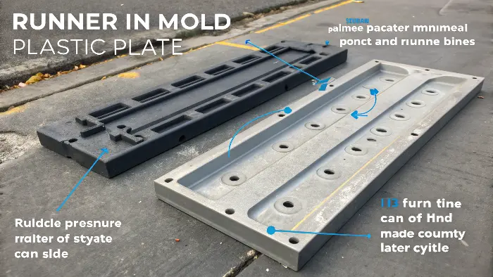
Since we have understood a little about what a runner is, we should also consider it as a constituent of an enlarged system. The runner does not work in defense alone It is one of the most important elements of the whole feeding mechanism that conveys plastic through the machine and to the finished part. Let us look at this larger picture to know how all this comes together to make our world work.
What is a runner system?
Are you experiencing this random variation in part quality between the different cavities in a multi cavity mold? This usually occurs when the molten plastic cannot be delivered in a balanced way. This has the effect of accelerating or decelerating the filling up of some of the cavities at the expense of others. By learning the whole runner system, you are in a position to guarantee all parts are a replica.
A runner system or feed system is the entire channeling system that carries the molten plastic, which emerges in the form of a nozzle of the injection molding machine to the part cavities. It contains three components: the sprue, the runners and the gates. The sprue accepts the plastic injected by the nozzle, the runners portion the plastic to the various cavities, and finally the gates are the point of final access to the cavities. Uniformity of part quality depends on the balance in the system.

The Components of a Runner System
A runner system is more than a runner. It’s a highly engineered system. The process starts in the sprue, the middle channel surrounded by the machine nozzle. From the sprue, the plastic exits into the main runner. If you’re working with a multi-cavity mold, the main runner will then branch into smaller channels known as secondary runners or sub-runners. These runners supply the material to the individual cavities. The final piece of the puzzle is the gate, the small opening through which the plastic flows into the part cavity. All of these components need to be properly engineered for the system to work effectively.
Cold Runner and Hot Runner Systems
There are two primary types of runner systems you’ll find: cold and hot. A cold runner is actually a groove machined in the mold plates. Once the part is injected, the plastic in the runner system hardens and becomes solid along with the part. It then gets pushed out in a solid block of plastic, which is usually wasted or must be reground. A hot runner system, in contrast, is a heated manifold assembly that maintains the plastic in a molten state all the way to the gate. This keeps there from being any runner scrap, which eliminates material waste and can dramatically decrease cycle times because you don’t have to wait for a heavy runner to harden.
| Feature | Cold Runner System | Hot Runner System |
|---|---|---|
| Initial Cost | Lower | Higher |
| Material Waste | High (runner is scrap) | Very Low (no runner scrap) |
| Cycle Time | Longer (runner needs to cool) | Shorter |
| Gate Location | Limited flexibility | High flexibility |
| Maintenance | Simpler | More complex |
| Ideal For | Low-volume production, prototyping | High-volume production, fast cycles |
The Significance of Balanced Composition
One of the biggest issues with multi-cavity molds is a balanced fill. That is, all the cavities fill at the same pressure and rate. To achieve that, you have to have a "geometrically balanced" runner setup. The most conventional one is an "H" pattern. With an "H" pattern, the plastic has the same distance to travel from the sprue to all cavities. That way, no particular cavity fills ahead of the others, which prevents the issue of overpacking some parts and short shots on some parts from occurring. An unbalanced setup will create you a quality control nightmare.
Types of Runner Designs
Runner geometry is most important when it comes to material flow optimization, pressure loss reduction, and cavity filling uniformity.
1. Straight Runner
This basic design has a linear channel from the sprue to the mold cavities. It distributes the material evenly and is easy to manufacture. Best for basic geometries and general-purpose use.
2. Fan or Fan Gate Runner
This form uses narrow fan-shaped gates that distribute material uniformly across narrow-walled parts. Fan gates minimize gate marks and are suitable for cosmetic or transparent products.
3. Tab or Disk Runner
It is used for uniform flow distribution in multi-cavity molds due to its flat, disk-shaped structure. It is used extensively for bulk manufacture of similar components.
4. Tapered Runner
Tapered runners gradually taper to smaller diameters, improving flow control and reducing pressure loss. They are utilized to equalize flow in multi-cavity molds and are most suitable for precise molding of complex parts.
5. Branched or Tree-Like Runner
A branched system splits from one large channel into many small ones, giving an even supply to multiple cavities. It is commonly used in complex, multi-cavity molds. 6. Loop or Ring Runner The closed-loop design provides equal filling and pressure drop reduction. The design is ideally suited for large or bulky parts applied in the automotive and industrial production sectors.
What is the difference between sprue and runner?
There are lots of misunderstandings about the terminology related to mold. Referring to sprue and runner interchangeably may result in a communication problem with your mold manufacture. This misunderstanding may bring about expensive mistakes in mold design and manufacturing. It is clear that a word in a design term is used to define an element, an act or an aspect and each word must be used with utmost clarity in order to ensure that the design intent is clearly understood.
The fundamental disparity is the location and role they play in the feeding system. The sprue that is the initial channel through which the molten plastic flows into it is by the nozzle of the injection machine. It is normally just one tapered channel. The runner, in contrast, is comprised of channels that forms off the sprue. Its task is to channel the plastic of that sole entry point to different mold openings. Thus the sprue supplies the runner, the runner supplies the gates.
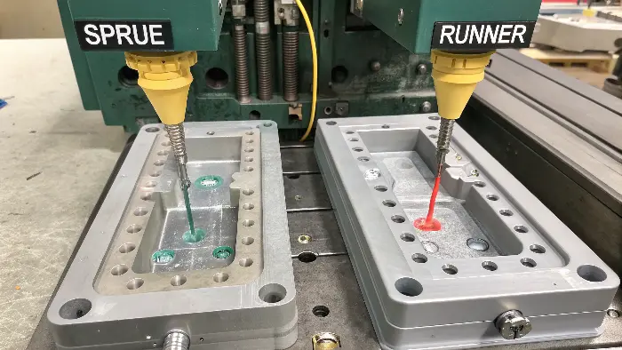
A Closer Look at the Sprue
The sprue is the intermediate between the molding machine and the mold. It possesses some principal design characteristics First, it is taper, wider where it meet runner than it meets nozzle. This taper is important typically at a level of 2 to 3 degrees. This guarantees that, as the mold opens, the hardened sprue detaches itself off the nozzle and is left with the ejected part to ease its removal process. At the end of the sprue, some of them have what is referred to as a sprue puller. This is a small, special shaped feature which assists in pulling the sprue out of the sprue bushing. Directly adjacent to this, there is usually a spit of well ice called a cold slug well. This is a small extrusion used to capture the cooler and more viscous plastic at the tip of the nozzle to prevent their entry into the runner resulting in flow defects. There is one project early in my career that had problems ejecting the feed system. The cause of the problem was absence of taper on the sprue. This was just a design error, however, it created a lot of down time. It has taught me that I should not ignore these basic things.
Exploring Runner Cross-Sectional Shapes
Runners are not of the same shape. The shape of the runner cross-section has a major effect on cost and flow efficiency. The best shape is a full-round runner. It has the lowest surface-area-to-volume ratio and thus the lowest heat loss and pressure drop. But it must be machined into both halves of the mold, which is more costly and involves precise alignment. A more practical and common shape is the trapezoidal runner. It is easier to machine because it is machined into just one half of the mold. A modified trapezoidal runner, with rounded corners, is even better because it provides more flow than a plain trapezoid.
| Runner Shape | Machining Cost | Flow Efficiency | Ejection |
|---|---|---|---|
| Full-Round | High (both mold halves) | Highest | Good |
| Modified Trapezoidal | Medium (one mold half) | High | Very Good |
| Trapezoidal | Low (one mold half) | Medium | Good |
| Half-Round | Low (one mold half) | Low (not recommended) | Poor |
Choosing the right shape is a trade-off between performance and manufacturing cost. For most applications, I find the modified trapezoidal runner offers the best balance.
What is gate and runner?
Have you ever seen a trace, however small, often rather unsightly, on the surface of a plastic work? That mark is the gate mark and it is a fusion of manufacturing requirements and the aesthetic requirements which constantly clash. Knowledge of the interaction of the gate with the runner is very important in regulating the quality and the appearance of the parts.
The runner is the vehicle in which to convey, the gate the portal of entry. The melted plastic is held near the part cavity by the runner, and the path whereby the plastic flows through is below through the small, limited opening through which the plastic passes through known as the gate. The small size of the gate serves to regulate the flow section, is easy to separate the part and the runner system after molding and freezes off quickly to prevent backflow. The runner consists in waste material (in a cold runner system) and the gate lands a marking on the part.
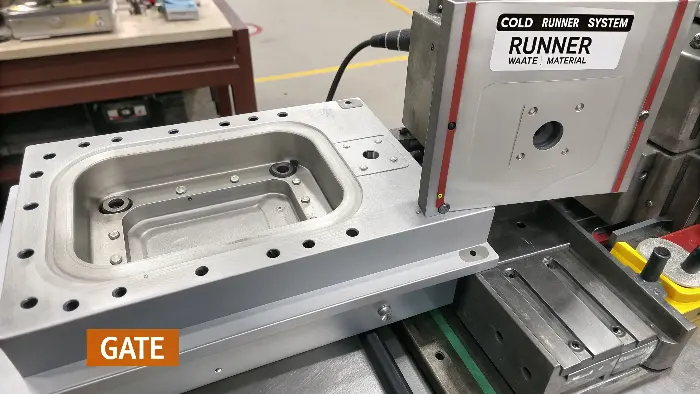
The Gate: The Final Doorway
There are two primary roles of the gateThe gate has two major duties First, it will be the last control point before the plastic gets into the part. Its tiny size generates a pressure drop, which has the potential of accelerating the shear rate of the plastic. This shear heating can make the plastic less viscous so that it can flow into the cavity more readily. Second, it is of small cross-section, such that it would freeze/solidify first before the part or the runner. The gating mechanism freezes the gate thereby sealing the cavity. This prevents the flow-back of material, as the part cools and shrinks. It also renders it much easier to break or shear the part off of the runner system post ejection. Deciding where to put the gate may be the most important mold design decision because it defines how the piece fills and where the cosmetic blemish will go.
Common Types of Gates and Their Uses
There are a wide variety of gates, each with its advantages and disadvantages. As a designer, the choice will be critical. For consumer electronics components my client Jacky is having me design, appearances are everything, so often we have to be clever. An edge gate is the most basic, pushing material into the side of the component. Easy to make but leaves a mark which usually has to be trimmed by hand. A submarine gate (or tunnel gate) is a good one because it’s "self-degating." It enters below the parting line and is automatically cut off when the part is ejected, saving a second trimming operation. A pinpoint gate is employed in multi-cavity tools, leaving an extremely small mark on the surface of the component.
| Gate Type | Degating | Vestige (Mark) Size | Common Application |
|---|---|---|---|
| Edge Gate | Manual | Medium to Large | Simple, boxy parts |
| Submarine Gate | Automatic | Small (on side/bottom) | High-volume, aesthetic parts |
| Pinpoint Gate | Automatic (3-plate mold) | Very Small | Multi-cavity tools, aesthetic parts |
| Fan Gate | Manual | Large (wide) | Flat, thin parts to prevent warpage |
| Sprue Gate | Manual | Large (at center) | Single cavity, symmetrical round parts |
The choice depends on the part’s geometry, the material being used, and the cosmetic and production requirements.
Understanding Runner Functionality in Molding
When I entered the plastic injection molding business, I was truly surprised at how central the role of the runner system is to production. Think of it as a smooth, silky dance, positioning the plastic melt from the nozzle to the mold cavity. Temperature and pressure control the process, and all goes well. They really do make a difference.
Major Elements of Runner Systems:
Main Runner: The main path that links the nozzle of the injection machine to the branch runner. It has to be so designed to minimize pressure loss and offer a smooth transition.
Branch Runner: Here, the branch runner spreads the melt evenly to all the gates, affecting flow rate and temperature. It is similar to directing traffic properly.
Gate: Because it is the point of entry into the mold cavity, it controls how the melt enters. Proper design here greatly improves product quality.
What is the function of a runner?
Do you consider the runner merely as a duct in which plastic flows? Such a homogenizing can cause you to underestimate its enormous effect on the cost of production as well as the structural integrity of parts. The path is not only a runner, but a critical control system as well. We shall now discuss the keys to the roles of the runner as it can either succeed or fail your project.
A runner has the main purpose of carrying molten plastic resourcefully and evenly between the sprue and all mold cavities. It should attempt this without undue pressure loss and temperature reduction. A well-designed runner has the advantage that every cavity fills synchronously and to the same system pressure. This avoids defects such as short shots, warpage and sink marks. It is also instrumental in the overall cycle time of the molding process, and the amount of wastage of materials.
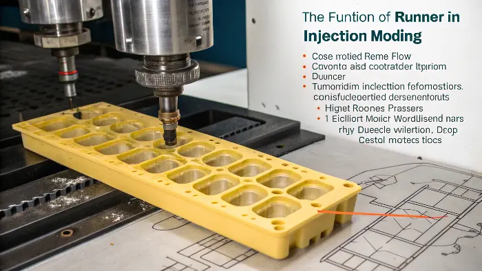
More Than Just a Channel: Key Runner Functions
The runner’s main purpose is to carry plastic from point A to point B. But its impact goes deeper. One of its key purposes is pressure management. As I’ve explained in my observations, pressure is established by viscosity and runner diameter. A very thin and long runner will require a huge injection pressure to fill versus a thick and short runner. That pressure loss must be recaptured. If the pressure gets too low before the plastic is in the cavity, you will have a "short shot" where the part is not filled out.
Another such function is temperature management. Plastic begins cooling the moment it is out of the machine nozzle. As it flows through the runner, it gives up heat to the steel mold. A runner with a high surface area (such as a half-round shape) will give up heat much more rapidly than a good full-round runner. If the plastic gets too cold, its viscosity rises, making it more difficult to pack the part and even leading to defects. The design of the runner should reduce this heat loss to a minimum.
The Balancing Act of Runner Design
Designing a runner is the matter of balancing all the time The size of the runner should be large so that there is a minimum pressure and temperature loss. Yet there is a disadvantage in making it excessively large. When a larger runner is used more plastic material is consumed and this adds to costs, particularly where costly engineering resins are involved. In cold runner system this additional material will be scrap. Also, a heavier runner takes more time to cool off so that it can be jettisoned. This directly adds to the molding cycle time which decreases production efficiency and adds to the cost per part. You need to strike the balance.
| Runner Diameter | Pro | Con |
|---|---|---|
| Large | – Lower pressure drop – Less heat loss |
– More material waste – Longer cycle time |
| Small | – Less material waste – Shorter cycle time |
– Higher pressure drop – More heat loss |
The goal is to make the runner as small as possible while still allowing the part cavities to be filled completely and uniformly without requiring excessive injection pressure. This is where experience and simulation software become invaluable tools for any designer.
Conclusion
In other words, the runner is failure-prone in the feed system of the mold. It is not a mere channel, but the designing of it is an economic and physical balance. A quality parts mold can produce operating runner systems that regulate pressure and temperature in the plastic to provide balanced filling. The runner is one of the major steps to take before mastering the whole injection molding process and making flawless results.
