Are your sheet metal components blemished by assembly issues or unexpected costs? Most often than not, they are the product of failing to take hardware integration into account at the design phase. This creates rework and unnecessary costs. What if you could anticipate these issues ahead of time, so that manufacturing is eased and the end product is enhanced?
DFM (Design for Manufacturability) sheet metal fabrication hardware guidelines give importance to part design with hardware consideration right from the beginning. It involves deliberate selection of materials, precise hole location, proper tolerance, and smart design choices like efficient bend radii. Hardware installation process and specifications in plain language are required to improve manufacturability, cost savings, and quality.
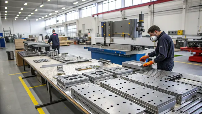
The initial step is to comprehend these principles. Now, let’s explore how specific DFM considerations for hardware can transform your sheet metal designs from concept to reality, making the entire process more efficient. I’ve seen many projects benefit from this approach.
How Do Precision Features, Like Those Made with Doweling Tools, Affect Sheet Metal DFM?
Ever wrestle with misaligned sheet metal parts during assembly? This all-too-familiar headache usually is the result of an inaccuracy in feature location. When parts don’t fit, the line stops and expenses increase. There has to be a better way to guarantee accuracy from the beginning in design.
Precision features like dowel pin holes made with precision doweling tools are essential in sheet metal DFM. They guarantee correct assembly alignment and positioning of the parts. Making the features in their proper form from the very beginning, with the right tolerances and material in mind, avoids the assembly issues and enhances the integrity and uniformity of the final product..
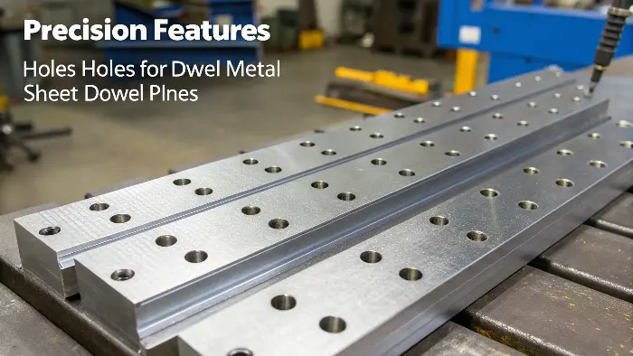
Features that determine how pieces fit together are frequently mentioned when discussing precision in sheet metal. For example, dowel pins are straightforward but remarkably efficient in guaranteeing consistent alignment. Early on, I discovered the hard way that relying solely on general tolerances or "eyeballing" important alignment spots was a surefire way to fail. Here, the DFM method entails not only defining the dowel’s hole but also taking the material’s response to the doweling process into account.
Key DFM Aspects for Precision Features:
- Tolerances for Holes: The dowel pin-to-hole fit (press fit, slip fit) is very important. This needs to be well defined according to the application.
- Material Considerations: Softer materials get distorted if press fits are too tight, while harder materials require finer machining.
- Yes, Tooling Access: Is the doweling tool or press able to reach the specified location without hindrance from other features?
- Distance to Edges/Bends: Accurate holes drilled too close to edges or bends may cause material warping.
A carefully planned design with such precision elements cuts assembly time substantially and improves overall quality. It’s less about micro-managing and more about foresight regarding how these small details affect the grand scheme of manufacturing.
| Feature Consideration | DFM Implication | Example Solution |
|---|---|---|
| Alignment Accuracy | Prevents assembly rework | Specify dowel pin holes & tolerances |
| Material Hardness | Affects hole creation and fit | Adjust tolerance based on material |
| Tool Access | Ensures features can be physically created | Design for clear tool paths |
| Feature Proximity | Avoids material distortion during manufacturing | Maintain minimum distances |
What DFM Strategies Are Key for Integrating Specific Hardware, Like a Stainless Steel Touchless Exit Button?
Have you ever specified a sophisticated sheet metal enclosure, only to discover that the hardware you’ve specified, such as an advanced touchless switch, won’t fit or won’t operate properly? This is one of the most common sources of significant delays and redesign expense. Designing with off-the-shelf components means you must think ahead.
The main DFM methods for the implementation of some hardware, such as a stainless steel touchless exit button, involve the advance procurement of detailed hardware specifications. They cover cutout sizes, mounting, material compatibility (specifically with stainless steel), and clearance. Creating the sheet metal part to accommodate these elements with absolute accuracy produces an interference-free fit and proper functioning.
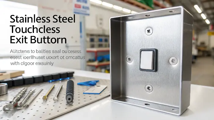
Including elements such as a "DFM WEL2261 Stainless Steel Touchless Exit Button" (a fictitious example based on your list) emphasizes how crucial it is to treat hardware as an essential component of the design rather than an afterthought. I remember a project where we selected a stylish button, but its mounting mechanism required more internal clearance than our compact enclosure design allowed. That was a lesson in getting datasheets first!
DFM for Specific Hardware Integration:
- Datasheet Diligence: Always get the manufacturer’s datasheet for any hardware. This is where you get key dimensions, mounting patterns, and material information.
- Cutout Design: Cutout size and shape must be precise. Consider laser cutting or punching capability. For stainless steel, special tooling might be needed.
- Mounting Provisions: To what does it mount? Screws, clips, adhesives? There are corresponding holes, tabs, or surfaces on the sheet metal to be prepared. For instance, PEM fasteners are commonly used.
- Material Compatibility: If using a stainless steel button, be sure that it will not galvanically corrode the sheet metal enclosure material if both are not the same metal in a corrosive environment.
Keeping these in mind beforehand saves a lot of trouble. For example, the "touchless" functionality can be sensor clearance or dedicated non-metallic regions if it’s capacitive sensing-based. It all circles back to sheet metal design.
| Hardware Aspect | DFM Consideration | Example Action |
|---|---|---|
| Dimensions & Cutout | Precise fit, avoid interference | Use datasheet for exact cutout, add tolerance |
| Mounting Mechanism | Secure attachment, ease of assembly | Design for specific screws, PEMs, or clips |
| Material | Durability, aesthetics, compatibility | Match or ensure compatibility with enclosure material |
| Special Features | Functional requirements (e.g., sensor range) | Provide necessary clearances or non-conductive areas |
What Factors Affect DFM?
The goal of DFM is to reduce manufacturing cost without reducing performance. In addition to the DFM principles, there are five parameters that may affect design for manufacturing and design for assembly:
1. Minimize Number of Parts
Reducing the number of parts in a product is the quickest way to reduce cost because you are reducing the amount of material you need, amount of engineering, manufacturing, labor, to shipping cost.
2. Construct Modular Assemblies
Using non-tailored modules/modular assemblies in your design allows you to modify the product without sacrificing overall functionality.
3. Design for Efficient Seek opportunities
To connect parts without the use of screws, fasteners or adhesives.
Stay away from screws that are too long or too short, separate washers, tapped holes, round heads and flatheads.
4. Minimize Parts Reorientation During Assembly & Machining
Components should be designed in a way that little manual input is needed when producing them and putting them together
How Does DFM Optimize Sheet Metal Designs for Assembled Kits, Such as a DEF Flow Meter Kit?
Are you creating sheet metal components for intricate assemblies, such as a flow meter kit with nozzles? If the individual components of the kit aren’t thought of in the sheet steel layout, you might face an assembly nightmare with regions not fitting or unattainable contact topics.
**DFM designs sheet metal to optimize assembled kits, such as a "DEF Flow Meter Kit for Stainless nozzle," by emphasizing component interfaces, assembly and maintenance access, and solid mounting. This involves designing accurate mounting points, providing clearance to all kit components (such as nozzles and tubing), and the assembly sequence.
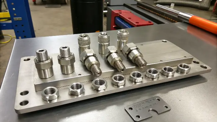
The DFM procedure becomes even more crucial when a sheet metal component is intended to integrate a complete kit, such a "DEF Flow Meter Kit for Stainless nozzle." There are numerous interdependent parts involved, not just a single piece of hardware. I have experience working on fluid handling system enclosures. The access required to connect the stainless steel nozzles at the intake and outlet, along with the tubing that goes with them, was entirely overlooked when we built the main unit’s flawless mounting. What was the outcome? A lovely box that was impossible to put together entirely.
DFM for Kits and Assemblies:
- Component Placement: Plan the placement of all the components of the kit into the sheet metal enclosure. Verify interferences using 3D modeling.
- Accessibility: Ensure that all points of connection, adjustment screws, and serviceable components are accessible in the assembled condition. This is important for initial installation and for future maintenance.
- Mounting Strategy: Every element of the kit might have different mounting requirements. The sheet metal must be provided with adequate holes, brackets, or standoffs.
- Cable/Tube Management: Route any wiring or tubing with the kit. This prevents kinking, rubbing, and makes assembly cleaner.
For instance, you would have to think about how much room a stainless nozzle takes up, how it is sealed, and whether it requires a certain orientation. DFM forces you to think through the entire lifecycle of the product.
| Assembly Aspect | DFM Consideration | Example Solution |
|---|---|---|
| Component Fit | All parts must fit without interference | 3D model checks, define clear zones for each component |
| Assembly Sequence | Parts must be installable in a logical order | Design for sequential, easy assembly steps |
| Serviceability | Allow for maintenance or replacement of kit parts | Provide access panels or removable sections |
| Connections | Easy access to nozzles, ports, electrical connections | Ensure clearance and tool access for all connections |
How to Use DFM?
Applying DFM is a formalized and team-oriented process that involves all firm teams involved. The most important steps in the DFM process are:
Design analysis:
Check the product design to identify possible manufacturing problems.
Alternatives evaluation:
Compare other alternative solutions for enhancing the design for manufacture.
Prototyping and testing:
Design prototypes to test various solutions and check if they work.
Validation and implementation:
Validate the optimal solution and implement it in the final product design.
Why is Detailed Design Documentation, Perhaps Like a ‘DFM DS 60B-1+2_EN.cdr’ File, Vital in DFM for Hardware?
Ever submitted a design to production and had them call back with a dozen questions about imprecise locations of hardware or omitted specs? This imprecision leads to delays and potential errors. Accurate, detailed documentation is the foundation of effective production.
Thorough design documentation, in the form of a document like ‘DFM DS 60B-1+2_EN.cdr’ (which would supposedly be a CorelDRAW design document), is essential to DFM hardware since it makes all information available in a clear-cut manner. It has precise dimensions, tolerances, material information, hardware part quantities, location notes, and special manufacturing comments so that all can understand.
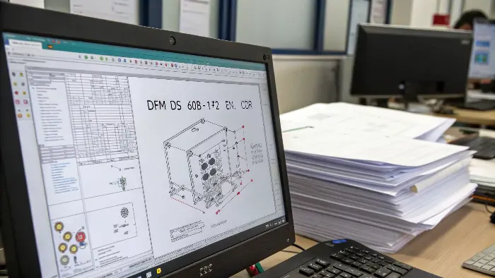
The title ‘DFM DS 60B-1+2_EN.cdr’ is exactly what it is, a specific design file, and it refers to an interesting fact: your design will only be as good as the documentation you do on it. I’ve seen great designs fail in production because the DFM drawings aren’t great or were sloppy. It’s like giving someone a recipe with half of the ingredients left out. The ".cdr" suggests a vector graphics file that is often used in layouts or profiles, and that’s a good start, but DFM documentation demands more.
Elements of Comprehensive DFM Documentation:
- Detailed Drawings: Complete dimensioned drawings (orthographic, isometric) with all details like holes, bends, and cutouts for hardware.
- Hardware Callouts: The exact locations and part numbers of all the integrated hardware (screws, nuts, standoffs, buttons, etc.).
- Material & Finish: Clearly specify the sheet metal grade, thickness, and finish required (e.g., anodize, powder coat).
- Tolerances: Define overall tolerances and any critical-to-function hardware mounting point specific tolerances.
- Assembly Instructions: Any intricate assembly instructions, especially where hardware installation sequence or torque values are involved.
A high-quality drawing or digital model file serves as the only reliable source of information. It avoids suppositions and guarantees that the component is manufactured as intended and prepared for hardware integration. At CKMOLD, we always highlight that clear contact through documentation is as essential as the method itself.
| Documentation Aspect | DFM Importance | Example Content |
|---|---|---|
| Dimensions | Ensures accurate manufacturing of features | All lengths, hole diameters, bend radii fully specified |
| Hardware Specs | Guarantees correct hardware is used and fits | Part numbers, supplier info, mounting details |
| Material Callout | Defines structural and aesthetic properties | e.g., "Stainless Steel 304, 2mm thick, #4 brush finish" |
| Special Notes | Highlights critical manufacturing or assembly steps | e.g., "Ensure deburring of all edges before finishing" |
What DFM Considerations Ensure Success with Specialized Components, Like an IP65-Rated S/Steel Exit Button with LEDs?
Designing to fit specialized components like an IP65-qualified stainless steel exit button with integral LEDs? Such components will have unique sealing, wiring, and visibility requirements. Not including these in the sheet metal design will compromise their protection rating and operation.
Specialty part DFM, e.g., an "DFM S/Steel Exit Button Green LED IP65," involves design consideration of sealing needs (for IP rating), LED wiring access, and indicator visibility. The sheet metal design must provide a compatible mounting surface, provide environmental protection, and neatly fill any electronics or wiring associated with it.
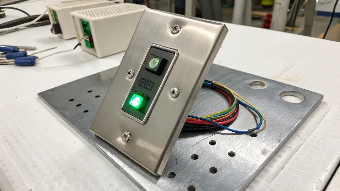
When you’re working with components with particular ratings or characteristics, such as an "DFM S/Steel Exit Button Green LED IP65," the DFM issues get more complicated. The "IP65" rating, for example, indicates it is dust-tight and water-jet protected.
This has very specific implications for how it gets mounted into the sheet metal. I remember one job where an IP-rated connector was installed, but the panel cutout was one-sixteenth of an inch too big, and it broke the seal. A small thing, a huge issue.
DFM for Specialized Hardware:
- Sealing Integrity: The sheet metal surface should be flat and smooth where it is to seal. The cutout should be accurate in order to allow the gasket (if used) to work. Surface finish should be considered.
- Connectivity and Wiring: What powers the LED? Where do wires originate? The sheet metal structure must allow for pathways or internal space for wiring without pinching or damage.
- Protection of the Elements: While the button itself can be rugged (stainless steel), the sheet metal enclosure can be required to offer some additional protection or to keep the button from being unintentionally triggered.
- Thermal Management (for LEDs): LEDs produce heat. An ordinary indicator LED on an exit button won’t be an issue, but it’s a DFM point – does any heat need to be passed through the sheet metal?
The green LED also implies a need for visibility. Where you place the button and the surrounding sheet metal design should not occlude it. These specialty components will often cost more, so ensuring that they function as specified through good DFM is critical to value.
| Special Feature | DFM Consideration | Example Sheet Metal Design Element |
|---|---|---|
| IP Rating (e.g., IP65) | Maintain seal integrity against dust/water | Precise cutout, flat mounting surface, gasket groove if needed |
| Integrated LED | Power, wiring, visibility, heat dissipation | Cable routing holes, space for small PCB, clear view |
| Material (S/Steel) | Durability, corrosion resistance, aesthetics | Appropriate cutout method for stainless, compatible finish |
| User Interaction | Ergonomics, accessibility, accidental actuation | Optimal placement, potential for shrouds or guards |
How Can DFM Principles Guide the Integration of Electronic Components, Such as a Voltage Convertor, into Sheet Metal?
Mounting electronic components like a voltage converter on a sheet metal assembly? It’s less a function of making it fit; you need to consider heat, electrical insulation, and rigid mounting. Poor planning here can create overheating, short circuits, or the components falling off.
DFM rules direct electronic component integration, say a "Voltage Convertor WVC12," through consideration of safe mounting, proper ventilation or heat sinking, electrical grounding or insulation, and wire accessibility. The sheet metal design must offer stable mounting points, take airflow into account, and allow safe operation of the electronics.
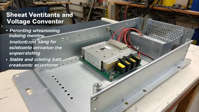
Installing something like a "Voltage Convertor WVC12" in a sheet metal layout poses a particular kind of DFM issues. Electronics are delicate. I’ve had cases where a converter was installed too close to a heat source in the enclosure and caused premature failure. Or, there were not enough grounding points in the sheet metal layout to cause noise problems.
Sheet Metal DFM of Electronic Components:
-
Mounting: The mounting holes or tabs are typically found on the voltage converters. Sheet metal requires standoffs, brackets, or PEM fasteners. Vibration resistance can also be a consideration.
-
Thermal Management: Converters produce heat. Airflow is considered during the DFM process. This may involve the inclusion of ventilation slots or ventilation patterns in the sheet metal, or provision for mounting the converter onto a larger metal surface to serve as a heat sink.
-
Electrical Safety & EMI: Sometimes adequate grounding of the sheet metal enclosure is required. Clearance of live electronic components from the metal chassis should be maintained to avoid shorts. Sometimes EMI shielding requirements influence the sheet metal design (e.g., gasketing, material selection).
-
Access Wiring: How will power and signals get to the converter? The layout needs to accommodate cables being routed and joined with ease, usually through cutouts or internal channels located in strategic positions.
Keeping these things in mind right from the start ensures the electronics function properly and safely in their sheet metal enclosure. It is all about creating a supportive and shielding environment for these critical components.
| Electronics Aspect | DFM Consideration | Example Sheet Metal Solution |
|---|---|---|
| Secure Mounting | Prevent movement, ensure good electrical contact if needed | Standoffs, PEMs, dedicated brackets, DIN rail clips |
| Heat Dissipation | Avoid overheating, ensure component longevity | Ventilation holes/slots, heat sink mounting provisions |
| Electrical Isolation | Prevent shorts, ensure safety | Adequate clearances, non-conductive barriers if necessary |
| Grounding/Shielding | Ensure electrical safety, reduce EMI | Designated grounding points, conductive gaskets for seams |
Conclusion
In the end, applying DFM best practices to sheet metal hardware design is not hard work, but smart design. By incorporating hardware into your design early on, you eliminate errors, save money, and create better, more reliable products. It’s a simple adjustment that rewards you every time.
