Struggling with slider failures might be a miscalculation of forces. This small error can lead to costly mold damage and production delays, hurting your bottom line and causing major headaches you just don’t need.
The simplest way to calculate the required force for a mold slider is to determine the force exerted by the injection pressure on the slider’s face and account for the locking angle. The core formula is F_actuator = (P_injection × A_slider / tan(α)) + F_friction. Here, ‘P’ is injection pressure, ‘A’ is the slider’s projected area, and ‘α’ is the locking heel angle. Always add a safety factor of 15-25% to ensure reliable, long-term operation.
Getting these calculations right is the bedrock of a solid, dependable mold design. Honestly, it’s one of those things that separates the pros from the amateurs. I’ve seen molds fail catastrophically because someone overlooked a simple force calculation. But before we get into the nitty-gritty of the slider itself, it’s super important to understand the bigger picture of forces at play in the machine. It all starts with the most basic question of all.
How much pressure is needed for injection molding?
Ever wonder why some parts have flash while others are short-shot? The wrong injection pressure is often the culprit. This guessing game costs you material, machine time, and quality control headaches that can slowly drain your profits without you even noticing.
Injection pressure typically ranges from 5,000 to 20,000 PSI (or about 35 to 140 MPa), but this is not a one-size-fits-all number. The right pressure depends heavily on the specific plastic material’s viscosity (its Melt Flow Index or MFI), the thickness of the part’s walls, and the complexity of the mold’s flow path. Simply put, thicker walls need less pressure, while thin, complex parts require much more.
Let’s dive a bit deeper into this because it’s a fundamental concept. Getting the pressure right is step one for everything else we’re going to talk about. Think of it as the power source for the entire operation. Too little power, and you don’t get a finished part. Too much, and you can cause some serious damage.
When we mention pressure, we’re really talking about two phases: injection pressure and holding pressure. The initial injection pressure is the high-pressure burst necessary to push the plastic melt and pack out 95-99% of the mold cavity in a rush. Then the machine changes to a lower holding (or packing) pressure. The second phase is necessary for packing out the part, compensating for material shrinkage on cooling, and giving good surface detail without over-stressing the mold.
So, what determines the right pressure? Three main things:
1. Material Viscosity: The "Syrup vs. Water" Analogy
Imagine trying to push honey through a straw versus water. The honey (a high-viscosity material like Polycarbonate) needs a lot more force than the water (a low-viscosity material like Nylon). It’s the same with plastics. The material’s Melt Flow Index (MFI) gives us a good idea of its viscosity. A low MFI means high viscosity, which means you’ll need higher pressure.
2. Part Geometry: The Road Trip
Think of the molten plastic’s journey as a road trip. A short, wide, straight highway (a thick, simple part) is an easy drive that doesn’t need much gas (pressure). But a long, winding, narrow country road (a thin-walled part with lots of features) requires you to keep your foot on the gas. The longer the flow path and the thinner the wall section, the more pressure you need to overcome resistance and friction before the plastic cools and solidifies.
3. Mold Temperature: Warming Up the Path
| If you run a mold too cold, the plastic will start to freeze the moment it touches the steel. This forces you to use extremely high pressures to fill the part, which can cause other problems. By running the mold at the correct temperature for the material, you keep the plastic flowing more easily, which in turn reduces the amount of injection pressure needed. It’s about working smart, not just pushing harder. Here’s a quick-and-dirty table to give you a feel for it: |
Material | Common Use | Typical Injection Pressure (PSI) | Notes |
|---|---|---|---|---|
| Polypropylene (PP) | Containers, toys | 5,000 – 10,000 | Very flowable, easy to mold. | |
| ABS | Electronics housing | 8,000 – 15,000 | Good all-rounder, moderate pressure. | |
| Polycarbonate (PC) | Lenses, safety shields | 12,000 – 20,000+ | High viscosity, needs high pressure. | |
| Nylon (PA66) | Gears, automotive parts | 7,000 – 14,000 | Flows well, but can be sensitive. |
This pressure is the very same pressure that will be pushing against your sliders, which is why getting this first step right is so critical.
How do you calculate injection force?
Are you just trusting the machine’s auto-settings for injection force? This can lead to inconsistent part quality and unnecessary wear on your mold. It’s a subtle problem that slowly eats away at profits by causing issues that are hard to trace back to the source.
Injection force is the total force the machine’s screw applies to push molten plastic into the mold. You calculate it by multiplying the injection pressure (in PSI or MPa) by the cross-sectional area of the injection screw (in in² or mm²). The simple formula is: Injection Force = Injection Pressure × Screw Area. This tells you if your machine is physically capable of doing the job.

Let’s break this down. It sounds technical, but the idea is pretty straightforward. The machine generates pressure, but that pressure is applied over a specific area—the face of the screw. The total push or force is a combination of these two things. A lot of people get injection force and clamp force mixed up, but they are totally different. Injection force pushes the plastic in, while clamp force holds the mold shut.
So, how do we put this into practice?
Step 1: Figure Out Your Pressure
This comes directly from what we just discussed. Based on your material, part design, and mold conditions, you’ll have an estimated injection pressure value. Let’s say for an ABS part, we estimate we’ll need around 10,000 PSI.
Step 2: Calculate the Screw Area
This is just basic geometry, something you probably learned in high school. The area of a circle is πr². So, you need to know the diameter of the injection molding machine’s screw. Let’s say the machine has a 50mm diameter screw.
First, let’s find the radius in the same units.
Radius (r) = Diameter / 2 = 50 mm / 2 = 25 mm.
Now, calculate the area:
Area = π × (25 mm)² ≈ 3.14159 × 625 mm² ≈ 1963.5 mm²
If you’re working in inches, just convert first. 50mm is about 1.97 inches.
Radius = 1.97 in / 2 = 0.985 in
Area = π × (0.985 in)² ≈ 3.05 in²
Step 3: Calculate the Force
Now, you just multiply the pressure by the area. Using our inch-based example:
Injection Force = 10,000 PSI × 3.05 in² = 30,500 pounds of force.
This number tells you the force the machine needs to generate. You can then check this against the machine’s specifications to make sure it’s not being overworked. Pushing a machine to its absolute limit day in and day out is a recipe for premature failure. For business owners like Michael, understanding this helps in selecting the right machine for a specific job, ensuring efficiency and longevity of the equipment.
How do you calculate the force of injection mould clamp?
Seeing flash on your parts? Your mold might be blowing open slightly during injection. This isn’t just a quality issue; it’s a huge safety hazard and a sign that your clamp force calculation is off, risking major damage to a very expensive tool.
To calculate the required clamp force, you first find the total projected area of all parts and the runner system on the parting line. Multiply this area by the average injection pressure inside the cavity. The basic formula is: Clamp Force (Tons) = (Projected Area [in²] × Cavity Pressure [PSI]) / 2000. Always add a safety factor of at least 10% on top.

This is one of the most critical calculations in all of injection molding. If you get this wrong, nothing else matters. The clamp force is the "hulk" force that holds the two halves of the mold shut against the immense pressure of the plastic trying to force it open.
I remember a project from my early days—a multi-cavity mold for a small phone accessory. We calculated the clamp force based on the parts alone and totally forgot about the large, winding runner system needed to feed all 8 cavities. On the first shot, the press sounded like it burped, and plastic shot out of the parting line. Flash everywhere! It was a messy, embarrassing, but very valuable lesson: always, always account for the runner.
Let’s walk through it.
Step 1: Calculate the Total Projected Area
This is the most misunderstood part of the calculation. "Projected Area" is the 2D shadow of your part (or parts) and runner if you were looking straight down the nozzle, perpendicular to the parting line. It’s not the total surface area. For a simple cup shape, it’s the area of the circle at the top, not the area of the walls.
So, you calculate the area of each part cavity at the parting line and the area of the runner system. Add them all together.
Total Projected Area = (Area of Part 1 + Area of Part 2 + …) + Area of Runner
Let’s say we have a 4-cavity mold. Each part has a projected area of 4 in². The runner system has a projected area of 2 in².
Total Projected Area = (4 × 4 in²) + 2 in² = 16 in² + 2 in² = 18 in².
Step 2: Determine the Average Cavity Pressure
This is the tricky part. The pressure inside the mold is not the same as the machine’s injection pressure. It drops as it travels through the nozzle, sprue, and runners. A common rule of thumb is that the average cavity pressure is about 30-60% of the machine’s injection pressure. For a rough calculation, let’s use 10,000 PSI as our starting machine pressure and assume a 50% drop, so our average cavity pressure is 5,000 PSI.
Step 3: Put It All Together and Add a Safety Factor
Now, we use the formula. The ‘2000’ in the formula is there to convert pounds to US tons.
Clamp Force (Tons) = (18 in² × 5,000 PSI) / 2000 = 90,000 / 2000 = 45 Tons.
Now, add a safety factor. I like to use at least 10-15%.
Required Clamp Force = 45 Tons × 1.10 = 49.5 Tons.
So, you’d need at least a 50-ton press for this job. Using a press that’s too small is asking for trouble. Using one that’s way too big is inefficient and wastes electricity. Getting it just right is key to a profitable operation.
Factors Affect the Clamping Force of the Mold
Clamping pressure for injection molding is pressure to keep the mold closed while filling the mold with liquid plastic. Insufficient clamping pressure will create flash (additional plastic coming out of the mold). Several significant factors dictate the amount of clamping pressure needed:
1. Injection Pressure
Increased injection pressure signifies greater pressure being exerted within the mold cavity.
This causes the halves of the mold to open and demands higher clamping force in an effort to maintain them closed.
2. Projected Area of the Part
The projected area is the area of the component (and any gates/runners) from the direction of injection.
Increased projected areas are exposed to increased force of injection pressure, which demands greater clamping force.
Equation: Clamping Force (tons)=Projected Area (in²)× Injection Pressure (psi) 2000 Clamping Force (tons)= 2000
Area (in²)×Pressure (psi)
3. Material Type
Different plastics expand by different amounts and have different viscosities.
High-viscosity materials like polycarbonate or reinforced plastics can require additional injection pressure and thus additional clamping force.
They also create greater internal cavity pressures.
4. Mold Design
Number of cavities: More cavities = larger projected area = larger clamping force required.
Venting, parting line fit, and accuracy: Low fit increases flash risk, necessitating higher clamp force.
Use of hot runner or cold runner can influence pressure distribution.
5. Wall Thickness of the Part
Thin-walled components need high-speed, high-pressure injection to fill rapidly before freezing.
This results in greater cavity pressure that requires more clamping force to keep the mold from opening.
6. Injection Speed
Higher injection rate lowers cavity pressure.
Increased speed will require harder pressing to prevent separation of the mold.
7. Gate and Runner System
The strength and nature of gate determine pressure transfer into the cavity.
Poor gate design can cause pressure peaks or irregular flow, yielding non-uniform forces within the mold.
8. Temperature and Cooling
Too much melt or mold temperature may expand the material or exert pressure. Asymmetrical cooling may lead to filament stresses, affecting the distribution of clamping forces. 9. Machine Tonnage and Tolerance The machine injection tonnage should be higher than the clamping force required. Practically, it is recommended to include a safety margin (typically 10-15%) above calculated force to ensure proper sealing and to accommodate variations.
What is a T1 sample?
You’ve spent weeks, maybe months, designing and building a new mold. The steel is cut, polished, and assembled. Now it’s time for the first trial. Are you prepared for what comes next, or will you be scrambling to interpret the results?
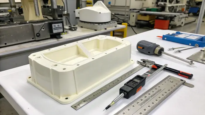
A T1 sample is the very first plastic part produced from a new injection mold. It’s typically run with the intended production material under basic, unoptimized machine settings. The T1 trial is the "moment of truth"—it’s not about making a perfect part, but about verifying the mold’s fundamental functionality and providing a baseline for any necessary corrections. It’s the first real-world test of all your design and force calculations.

For a business owner, the T1 report is one of the most important documents you’ll receive from your mold maker. It’s the proof in the pudding. It tells you if your supplier—someone like me at CKMOLD—has done their homework. A good T1, even one that highlights a few small issues, is a fantastic sign. It means the core engineering is sound. A disastrous T1, however… well, that’s a red flag that can signal major delays and cost overruns.
So what are we actually looking for when we run that first shot? It’s a comprehensive health check for the mold.
A T1 Trial Checklist: What We’re Really Testing
| Checkpoint | What We’re Looking For | What It Tells Us |
|---|---|---|
| Mold Functionality | Does the mold open and close smoothly? Do sliders, lifters, and ejectors move freely and correctly? Are there any worrying noises? | This is where our main topic—slider force calculations—is physically tested. If a hydraulic or angle pin slider hesitates, sticks, or slams, our math was wrong. |
| Part Formation | Is the part fully formed (no "short shots")? Is there any "flash" (plastic seeping out of the parting line)? | This is the direct result of our injection pressure and clamp force calculations. Short shots mean not enough pressure/force; flash means the clamp force is too low. |
| Dimensional Accuracy | How does the part measure up against the original 3D CAD model? We take dozens of measurements. | This checks the accuracy of the CNC machining and steel cutting. Are the critical dimensions within the specified tolerance? |
| Part Cosmetics | Are there any visual defects? We look for sink marks, weld lines, burn marks, scratches, or issues with the surface finish (e.g., texture). | This gives us clues about gate location, venting, and cooling. For example, sink marks often mean the holding pressure is too low or a cooling channel is in the wrong place. |
The T1 sample is rarely perfect, and that’s okay! Its purpose is to create a clear, data-driven action plan. After the T1 trial, we generate a detailed report with photos and measurements. This report will list any issues found and propose specific corrections. For example: "Flash observed on left side; recommend increasing clamp tonnage by 5%." or "Slight sink mark near rib; will modify gate to improve packing pressure in this area."
This leads to T2, T3, and so on. The T2 trial happens after the first round of corrections. Hopefully, it’s much closer to the final part. This iterative process continues until the part meets every single specification. 🔥
Conclusion
Calculating forces for injection molding isn’t just academic theory; it’s the practical foundation of a successful project. Getting the math right on injection pressure, clamp force, and especially slider actuation prevents costly errors, protects your investment in tooling, and ensures the quality and consistency of your final parts.
