It is frustrating when your well-crafted injection molded products emerge with defects. These defects are unproductive and pure waste of time, material and money and figuring out the exact root of the problem can sometimes seem like a complicated detective process. Unless you detect and correct the problem, you will only continue to produce bad parts which no designer or producer will desire.
In order to diagnose injection mold defects, first clearly identify the defect. Then, in a systematic fashion, examine the mold design, the process conditions (e.g., temperature, pressure, and speed), and the plastic material properties in use. Test techniques, like microscopy or material analysis, can be used to find the cause. Finally, take corrective and preventive measures to prevent repetition of the defect.
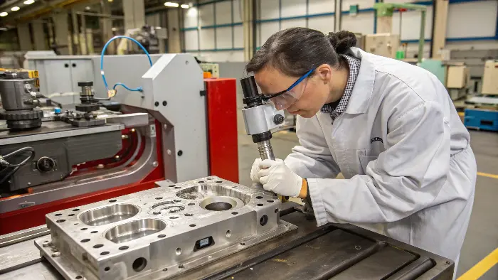
The defects issue is always prevalent in injection modeling and it is indeed an issue I have experienced, and many a time in my career, whether it was when I was in the early years of the factory floor or when I was running CKMOLD. Knowing what sort of defects they are is the most important first step to deal with them. Alright so, what type of hitch can we get into and how to go about it to get it out, and yes, I know this is always in the minds of every conscientious relevant designer and of course I talk of the likes of Jacky and his likes.
What are the defects in injection molding?
You’ve spent hours, maybe days, perfecting your product design, only to find the first molded samples are riddled with issues. These imperfections, from small blemishes to major distortions, can ruin the part’s look, its function, or both. Correctly identifying what type of defect you’re seeing is the very first step towards a solution, because different defects point to different underlying problems.
Some of the most prevalent injection molding defects include sink marks, warping, flash, short shots, burn marks, weld lines and voids. They all appear differently and typically signal potential defects in the mold itself, the moldable plastic, or the machine processing conditions. Detection of these specific defects is the principle of successful troubleshooting..
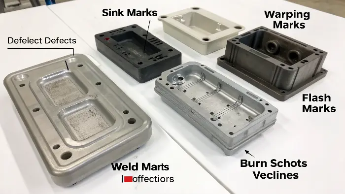
Let’s dive deeper into some of these common culprits. As someone who has seen thousands of parts, both good and bad, I can tell you that recognizing these defects quickly becomes second nature, but it’s essential to understand their typical causes.
Here’s a rundown of some frequent issues:
- Sink Marks: Dimples or depressions on the surface of the molded part. They will form on the backside surface of ribs or bosses, or in thicker part sections. The main cause is likely to be insufficient packing pressure while cooling, or uneven cooling where thicker sections contract more after the outer skin has hardened.
- Warping: When the component becomes distorted or bent from its initial form as it cools. It is primarily caused by differential shrinkage rates of the component due to non-uniform wall thickness, non-uniform mold cooling, or stresses caused by ejection.
- Flash: Flash is a light plastic excess that escapes from the mold cavity, usually along the parting line, or around ejector and core pins. It is usually a sign that the mold halves are not closing tight enough, injection pressure is set too high, or the mold is worn or damaged.
- Short Shot: This defect occurs when molten plastic fails to fill the mold cavity and therefore results in an incomplete part. This typically occurs due to injecting too little material, injection pressure or speed being too low, or blocked gates or runners.
- Burn Marks: These are brown or black discolored zones, typically at the end of the material flow path or in under-vented areas. They are the result of trapped air overheat by high-rate compression (e.g., a diesel engine effect) or by the plastic material itself being degraded due to high temperature or shear.
- Weld Lines (Knit Lines): These are lines or notches formed where two or more flow fronts of melted plastic cross and merge. If the melt fronts were too cold prior to their meeting, the weld will be poor, and this can result in a cosmetic flaw or a structural weak point.
Here’s a quick table summarizing these:
| Defect | Appearance | Common General Causes |
|---|---|---|
| Sink Marks | Surface depressions, dimples | Insufficient packing, uneven cooling, thick sections |
| Warping | Distortion from intended shape | Differential shrinkage, non-uniform cooling, internal stress |
| Flash | Thin excess material at parting line/pins | Low clamp force, high injection pressure, mold wear |
| Short Shot | Incomplete part, cavity not fully filled | Insufficient material, low pressure/speed, blocked gates |
| Burn Marks | Black/brown scorches | Trapped air, material degradation, excessive temperature |
| Weld Lines | Visible line where flow fronts meet | Melt fronts cooling too much before fusing, poor flow path |
This isn’t an exhaustive list, but it covers many of the common headaches that designers and molders face. Recognizing them is the first step to a cure.
How do you troubleshoot common problems such as defects or inconsistencies in molded products?
It is one thing to see defects in your molded products, but it is an all together different issue to be able to get them fixed. There are times when it may seem that you are ever just short of guessing, and switching settings one by one without a definite idea. However, a methodical technique may save considerable time, materials and frustrations and can get you to the real cause that much quicker.
When debugging defects, begin by describing and documenting the real defect. Then begin with the most basic and likely variables: material (is it the right type, is it dry?) and then the machine parameters (temperatures, pressures, speeds). If the issue still doesn’t go away, you will have to examine the mold design itself, considering such characteristics as gating, venting, and cooling. A step-by-step approach is always the best plan.
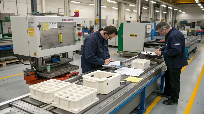
I’ve always found that a structured approach is key. When I started my own mold and CNC trading company, developing clear troubleshooting protocols was essential for helping my clients. Let’s break down a reliable method:
Step 1: Clearly Identify and Document the Defect
You have to be aware of the problem in advance before you act.
- What is the actual defect? (i.e., sink mark, flash, burn mark)
- Where on the part does it happen? Is it always in the same location?
- How often does it occur? Every individual piece? Every handful of pieces? At random?
- Get good, clear photos of the defect. Have good and bad pieces available to refer to. This record is priceless.
Step 2: Check the "Big Three": Material, Machine, Mold
I always tell people to start with the simplest and most common culprits.
- Material:
- Correct Grade? Is it the specified material? Has it been mixed with something else?
- Contaminated? Any visible foreign particles?
- Properly Dried? This is a huge one, especially for hygroscopic materials like Nylon, PC, or PET. I remember a client struggling for days with brittle parts; it turned out their Nylon pellets weren’t being dried to the manufacturer’s specification. Insufficient drying is a very common source of problems.
- Machine/Process Parameters:
- Temperatures: Check barrel temperatures (rear, middle, front zones), nozzle temperature, and mold temperature. Are they within the material supplier’s recommended range?
- Pressures: Look at injection pressure, holding pressure (packing pressure), and back pressure.
- Speeds: Injection speed and screw recovery speed.
- Times: Cooling time, holding time, overall cycle time.
- Crucially, compare current settings to a known good setup sheet if one exists. If you make changes, only change one parameter at a time and observe the result. Otherwise, you won’t know what fixed (or worsened) the problem.
- Mold:
- Venting: Are the vents adequate for the air to escape? Are they blocked with residue or flash?
- Cooling: Are the cooling channels clear and providing uniform temperature control? Is the mold temperature correct?
- Gating: Is the gate size and location appropriate? Is it worn or damaged?
- Parting Line: Is there any damage, wear, or debris on the parting line surfaces that could cause flash?
- Ejection System: Are ejector pins sticking, bent, or causing damage to the parts during ejection?
Step 3: Analyze and Test (If Necessary)
If the simple checks do not reveal the cause to you, you might need to dig deeper.
- As I have already indicated in my first insight, at times advanced testing methods like microscopy (to examine fracture surfaces or impurities) or spectroscopy (to determine unknown substances or impurities) can prove to be very helpful.
- For complex, long-term issues, a Design of Experiments (DOE) solution can be used. This is a more formal statistical method of identifying which of the parameters have the most effect on the defect.
Step 4: Implement Corrective and Preventive Actions
Once you’ve identified the likely cause:
- Make the necessary adjustments to the material, process, or mold.
- Document all changes made and the results. This helps build a knowledge base for future troubleshooting.
- Update your setup sheets with the new, optimized parameters.
- Consider if any long-term fixes are needed, such as mold modifications (e.g., adding vents, improving cooling, changing gate location).
This systematic process will guide you to solutions much more efficiently than random adjustments.
What is the main root cause for burn mark defect in injection molding?
The existence of those ugly black or brown streaks on your parts, in other words, the so-called burn marks, are sufficient indication that something is going amiss when having the injection. They do not only make the part stylish, but they can also show the degradation of the materials, which can decrease strength. Investigating the reasons why these burns are occurring is important in enabling them to make quality components.
The primary underlying reason of the burn mark defects in injection molding process is generally entrapped air getting instantaneously smashed and heating to the sizzling point that burns the plastic (the diesel-like effect). The other big cause is the plastic degradation of its own material due to excess temperature, long staying time within the barrel or adheres to high shear rates.
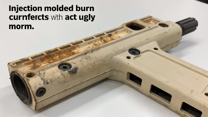
I’ve seen my fair share of burn marks, and they often appear in predictable places if you understand the mechanics behind them. Let’s explore these causes in more detail:
Trapped Air and the Diesel Effect
This is probably the most common reason for burn marks.
- Mechanism: As molten plastic rapidly fills the mold cavity, it compresses any air trapped inside. If this air cannot escape quickly enough through vents, the rapid compression heats it to extremely high temperatures – high enough to scorch or burn the plastic material it comes into contact with. This is very similar to how a diesel engine ignites fuel without a spark plug, simply through compression.
- Common Locations: Burn marks due to trapped air often occur at the end of the material flow path, in deep ribs or bosses, or in any area where air can get cornered.
- Solutions:
- Improve Venting: This is key. Ensure existing vents are clean and not blocked. Add new vents or enlarge existing ones in the problem areas. Vents are tiny channels (usually 0.01mm to 0.05mm deep) that allow air to escape but are too small for the plastic to flow through.
- Reduce Injection Speed: Slowing down the injection speed, especially towards the end of the fill, can give the air more time to escape through the vents.
- Optimize Gate Location: Sometimes, changing the gate location can alter the flow path and prevent air from being trapped.
Material Degradation
The plastic itself can break down and leave burn marks if treated roughly.
- Increased Melt Temperature: Whenever the barrel temperature or the nozzle temperature is established too high with respect to the material in process, the material will start to char and degrade.
- Long Residence Time: The plastic material, if it is exposed to the hot barrel for an extended period before injection (for example, due to the cycle time being very long or the machine is too large for the shot size), will break down.
- High Shear Rate: Excessive shear can generate friction heat. This may happen when the injection rates are excessive, or the material is forced through gates, runners, or a constricted nozzle that are too narrow.
- Solutions:
- Reduced Melt Temperature: Reduce the barrel and nozzle temperatures to the suggested range offered by the material supplier.
- Reduce Residence Time: Wherever possible, use a machine with a barrel volume that is closer to the shot size. Reduce unnecessarily long cycle times.
- Gate/Runner Design Optimization: Optimizing gate and runner design to prevent over-shear.
- Reduce Injection Rate: This reduces shear heating.
- Search for Obstructions: Plugged tip or hot runner can also cause overheating and material degradation.
I remember one project, in which there were burn marks continually springing up at the extreme point of a long thin core. We did run checks on any of the suspects we knew about. At last we found that just at that point was a small vent which you can hardly see with the naked eye and the residue had filled it up entirely. The solution was simple and thorough cleaning of that vent solved the problem instantly! It underlines the importance of even the trivial details.
Here’s a table summarizing these causes and solutions:
| Cause Category | Specific Reason | Potential Solution(s) |
|---|---|---|
| Trapped Air | Inadequate or blocked vents | Add/improve vents, clean existing vents, ensure proper vent depth and land length |
| Injection speed too high | Reduce overall injection speed, or use a profiled injection speed (slower at end) | |
| Material Degradation | Melt temperature too high | Lower barrel/nozzle temperatures |
| Residence time in barrel too long | Use appropriate machine size, minimize cycle time, purge old material | |
| Excessive shear (gates, runners, screw speed) | Enlarge gates/runners, reduce injection speed, reduce screw RPM during recovery | |
| Dead spots or blockages in nozzle/hot runner | Clean nozzle and hot runner system, check for worn screw/barrel components |
Addressing burn marks often involves a combination of adjusting process parameters and ensuring the mold is in good condition with adequate venting.
What are the causes of sink marks, and what are the prevention and correction strategies for sink marks in injection molding?
Sink Marks
Sink marks are surface depressions or indentations of injection-molded components, usually in thicker regions where the outer case cools and solidifies before the inner material.
Sink marks are basically empty spaces that are created because of the lack of pressure within the mold cavity while cooling and solidifying. Sink marks occur more readily in designs containing different wall thicknesses.
Common Causes of Sink Marks
The main reason for sink marks is the difference in cooling rate between the thicker and the thinner part sections. Lack of pressure during the pack stage of the injection molding process also causes this defect.
Prevention and Correction Strategies
Prevent sink marks by maintaining even wall thickness throughout the part design. A change in the holding pressure and time also has a positive effect, as it offsets the material shrinkage in thicker areas. Further, optimizing the cooling system within the mold to provide even cooling can go a long way in minimizing the occurrence of sink marks.
What causes contamination in injection molding?
What you want is products that are perfectly uniform in the most pristine plastic form, but you end up getting them with some specks and streaks of another color along with other flash marks or other spoilers. This is contamination, an irritating fault that may prove to be quite difficult to track back to its origin since it may originate in so very many ways in the manufacturing environment.
In injection molding, contamination is mainly by inadvertent additions of foreign particle or other kinds of plastic that mixes with the main source of raw materials. Usual causes are dirty hoppers or loaders, regrind problems, sectional air or material dust or grit anywhere in the workshop, incorrect material handling methods, or leftover material in the machine after the prior run.
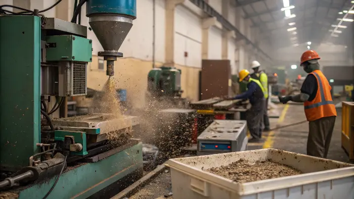
Tracking down the source of contamination requires a bit of detective work, much like finding the cause of other defects. I’ve seen contamination derail production schedules more than once, so understanding its origins is key to prevention.
Let’s look at the common participants:
Material Handling and Storage
This is a very frequent source.
- Dust and Dirt: Open material containers (bags, gaylords, hoppers) can easily collect airborne dust, dirt, or other debris from the factory environment. I’ve even seen instances where cardboard dust from material bags themselves became a contaminant.
- Mixing Materials: Accidentally mixing different types or grades of plastic. For example, a few pellets of ABS getting into a batch of polypropylene can cause significant issues. Clear labeling and dedicated handling equipment for different materials are vital.
- Improperly Cleaned Equipment: Grinders used for regrind, if not cleaned thoroughly between materials, can introduce contamination. The same goes for loaders, hoses, and drying equipment.
Machine and Auxiliary Equipment
The equipment itself could be the reason.
- Prior Run Residue: This is particularly prevalent during color changes. Unless the barrel and screw are properly purged, traces of the previous color or material will bleed into the new run and create streaks or off-color parts. Certain colors, such as red, can be particularly difficult to purge out.
- Degraded Material: Degraded material built up on the screw, barrel walls, or in the nozzle can flake off and leave black specks or colored streaks on the parts.
- Leaks: Oil or grease leaks from the machine (e.g., lubrication points, hydraulic system) will sometimes find their way into the material path or onto the mold.
- Wear Particles: Rust or metal particles can be brought in due to worn components like the barrel, screw, or even the mold.
Workshop Environment
The surrounding area plays a role.
- Airborne Contaminants: Dust, fibers, insects, or even particles from nearby processes (like grinding or painting) can settle into open material containers or directly onto the mold surfaces.
- Operator-Introduced Contaminants: Though less common with good practices, particles from operators’ clothing, hands, or tools can inadvertently be introduced.
Regrind Quality
Reusing reground material is cost-effective, but it requires caution.
- Dirty Regrind: If the material being ground was already dirty, or if grinding adds contaminants to the material (e.g., from a dirty grinder), then utilizing this regrind will continue the issue.
- Too High a Regrind Percentage: Too high a regrind percentage can at times lead to low-level contaminants aggregating which are not apparent while processing lots of virgin material.
Prevention Strategies are Key
Preventing contamination is always better than trying to fix it later.
- Good Housekeeping: Maintain the molding shop in a neat and clean condition. Clean the floors, machines, and auxiliary equipment regularly.
- Proper Material Handling: Store material containers covered. Utilize separate scoops and loaders for varied materials where practicable. Follow a "first-in, first-out" (FIFO) material utilization.
- Thorough Purging: Use proper purging compounds and procedures when changing materials or colors.
- Routine Maintenance: Check and clean machines, molds, and auxiliary equipment on a regular basis. Check for wear or leaks.
- Filtering: Apply magnetic grates on hoppers to capture ferrous metal particles. Inline filters can be applied to material loading systems.
- Controlled Regrind Use: Ensure regrind is clean and dry. Set firm specifications on the maximum amount of regrind per product.
Here’s a table to summarize common sources and preventive measures:
| Contamination Source | Example | Prevention Method |
|---|---|---|
| Material Handling & Storage | Dust in open material bags, mixed material types | Keep containers covered, clear labeling, dedicated equipment, FIFO |
| Machine & Equipment | Old color residue in barrel, oil leaks | Thorough purging, regular cleaning, preventative maintenance, check for leaks |
| Workshop Environment | Airborne dust, debris from other operations | Good housekeeping, air filtration if needed, isolate molding area if possible |
| Regrind | Foreign particles in regrind, dirty grinder | Clean grinders thoroughly, inspect regrind quality, control regrind percentage |
| Additives/Colorants | Incompatible masterbatch, poor dispersion | Use compatible additives, ensure proper mixing and drying of masterbatch |
By being vigilant about these potential sources, you can significantly reduce the chances of contamination affecting your injection molded parts.
How does choosing a skilled and verified manufacturing company help get fewer defective parts?
Selecting a manufacturing partner, such as CKMold, that has expertise in typical defects of injection molding and how to troubleshoot them can prove helpful for your project. They are experts and know the difference between defective and excellent parts—made on time and within budget, and those spoiled by weld lines, jets, flash, sink marks, and other blemishes. Aside from being a seasoned on-demand manufacturing facility, the company also offers design consulting and optimization capabilities that allow us to assist every team in producing working, beautiful, high-performance parts as cost-effectively as possible.
Get in touch with CKMold today to find out more about their injection molding services.
Conclusion
The approach to analyzing defects in injection molds needs to be systematic and logical. It begins with identifying accurately the particular defect, followed by a systematic search of the material, process parameters and mold design. We acquire a better feel about solving common problems, such as burn marks or contamination because we have figured out the true cause of the problems, like we discussed above. This knowledge will eventually result in better quality parts and more efficient production as well as give you fewer headaches in your molding operations.
