
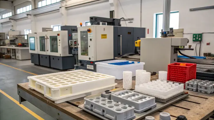
Mold contact has different roles during forming, cooling and release. Review which surfaces support the part and transfer heat, then identify where shrinkage, vacuum or friction may increase ejection loads. Machine clamping force is a separate calculation and is not a target contact force for the molded part.

Define Contact by Forming, Cooling and Release
There is no target percentage of part-to-mold contact. During filling the melt contacts the cavity/core surfaces that define its shape; after freeze and shrinkage, contact pressure redistributes and the part may grip a core, pull from the cavity or separate locally. The relevant question is whether the surfaces form, cool and release the part without unacceptable marks, deformation or damage.
During mold design, map cosmetic and critical surfaces, deep cores, ribs/bosses, texture, shutoffs and ejection. Wall transitions, gate/pack access and cooling influence shrinkage and contact, but no single variable determines contact by itself.

Use Release Evidence Instead of a Rule of Thumb
Draft, texture, polish direction, material shrinkage, draw depth, core stiffness, cooling and ejection area act together. A fixed draft or wall range should not be transferred across grades and features. Show draw direction, texture and appearance limits in the DFM review and document the exact-grade design basis.
At trial, inspect scuff, drag, whitening, deformation, pin/sleeve marks and retention side. Compare part temperature and release behavior by cavity and after repeated cycles; adjust geometry or steel when the acceptable process window is too narrow.

Tolerance Does Not Define Contact by Itself
Plastic-part capability depends on material, part design, tool layout, process and measurement state. The public overview of ISO 20457:2026 describes geometrical and dimensional tolerances and acceptance conditions for specified molding processes. It treats plastics differently from rigid metal parts; it does not establish one universal tolerance. Agree a separate inspection plan for cosmetic imperfections such as sink, drag marks and flow patterns. The public overview is not a complete acceptance specification.
Define functional datums, part age/conditioning, measurement temperature, fixture and cavity/sample plan. Separate dimensional acceptance from drag, witness, gloss and other surface limits.

Use Standards Only for Their Published Scope
ISO 20457 can support a plastics-specific tolerance agreement. ISO 294-4:2018 describes shrinkage measurements on injection-molded thermoplastic test specimens, including directions relative to flow. Such test data do not by themselves establish acceptance of a production part with different geometry and constraints. Quality-system standards and material test methods likewise do not prove that a particular molded part is compliant.
List the exact document/edition and the requirement it supports in the contract. Do not use a standards list as a substitute for the drawing, process, measurement and functional acceptance plan, and do not infer CKMOLD certification from a citation.

Core and Cavity Contact Create the Product Surface
The cavity side generally forms the outside and the core the inside, with contact determined by the geometry and shrinkage direction. Texture, draft, shutoffs and inserts define where the part can touch without damaging the surface or preventing release.
Contact Supports Cooling and Dimensional Stability
Good steel contact allows heat to move from the plastic into the mold, but thick sections, air gaps, coatings, inserts and poor cooling can interrupt that path. Uneven contact can produce local shrinkage, gloss or flatness differences.
Too Much Contact Can Create Release Problems
Identify the retention mechanism before changing the tool. Draft, texture, undercuts and uneven shrinkage can create mechanical resistance; vacuum requires a different check. DME’s air-poppet guidance explains timed air assistance for release and distinguishes it from gas venting during fill. Apply the selected component’s installation and operating requirements, then verify marks, distortion and reliable release.
Shrinkage Changes Contact During the Cycle
The part may initially contact both sides, then shrink toward the core or cavity as it cools. Packing, mold temperature, material, wall thickness and gate freeze influence this movement. A design should support the part where it needs control and allow release where it needs to move.
Validate Contact Through Release and Part Data
During mold testing and validation, observe ejection force where measurable, marks, vacuum, sticking, cavity wear, flatness, dimensions and surface. Compare cavities and repeated cycles under recorded conditions. Correct draft, polish, cooling, ejection or geometry only against the observed mechanism, then repeat the acceptance checks.
How Much Contact Should an Injection Molded Part Have With the Mold: Buyer Review Checklist
- Define which surfaces form, cool, support and release the molded part.
- Review draft, texture, shutoffs, inserts, cooling contact and shrinkage direction.
- Check vacuum, sticking, ejection force, air, polish and surface damage risk.
- Consider how packing, gate freeze, material and cooling change contact over the cycle.
- Validate release, flatness, dimensions, surface and cavity condition in trials.
FAQ
Should the molded part touch both core and cavity surfaces?
The geometry determines contact; some areas should be supported and cooled while other regions need draft or clearance for shrinkage and release.
Why does a part stick to the core?
Insufficient draft, texture, vacuum, shrinkage, roughness, undercut, poor ejection balance or excessive packing can contribute.
Conclusion
Evaluate contact through the part’s shape, cooling behavior and release evidence. Use draft, surface condition, shrinkage and ejection data to address sticking or distortion, and verify the result against dimensional and functional acceptance criteria.