Are you finding it hard to grasp the fundamentals of injection mold design? Many designers and engineers feel overwhelmed by the complexities at first. But without a solid understanding, you risk costly errors and production delays. This post will break down the essentials for you.
Injection mold design is the process of creating a specialized tool, the mold, used in injection molding to produce plastic parts. It involves defining the mold’s cavities, cores, runner system for plastic flow, cooling channels, and ejection mechanisms to ensure parts are formed accurately and can be removed easily.
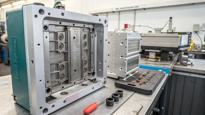
Understanding these basics is the first step to mastering how plastic parts come to life. I remember when I first started in a mold factory; getting these core concepts right was a game-changer. It helped me see how every detail in the design impacts the final product. So, let’s explore these fundamentals together, and you’ll see it’s not as daunting as it seems.
What is the introduction of injection molding?
Ever wondered how so many plastic items around us are made so precisely and quickly? It often seems like magic, but it’s a well-defined process. If you’re new to manufacturing, understanding this core technique is essential.
Injection molding is a manufacturing process for producing parts by injecting molten material into a mold. It’s widely used for mass-producing identical items, from small components to large car body panels. The material, usually a thermoplastic or thermosetting polymer, is fed into a heated barrel, mixed, and forced into a mold cavity, where it cools and hardens to the configuration of the cavity.
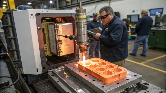
To dive deeper, injection molding is a cornerstone of modern manufacturing, especially for plastic parts. I’ve seen it transform businesses by enabling rapid, high-volume production. The process starts with plastic pellets. These pellets are fed into an injection molding machine.
Inside the machine, there are a few key stages:
- Feeding: The plastic granules are poured into a hopper, which then feeds them into the machine’s barrel.
- Melting & Mixing: Within the barrel, a large screw rotates. This screw does two things: it transports the pellets forward and it generates frictional heat, along with external heating bands, to melt the plastic. The screw’s design also helps in mixing the plastic for a uniform melt.
- Injection: Once enough molten plastic has accumulated at the front of the screw, the screw acts like a plunger. It pushes forward, injecting the molten plastic under high pressure into the mold.
- Cooling & Solidification: The mold itself is kept cool. When the hot plastic fills the mold cavity, it begins to cool and solidify, taking the shape of the cavity.
- Ejection: After the part has cooled sufficiently, the mold opens, and the solidified part is pushed out by an ejection system.
This cycle repeats, allowing for the production of thousands or even millions of identical parts. The beauty of injection molding lies in its ability to produce complex shapes with high precision and repeatability. It’s a versatile process used across industries, from automotive to medical devices, consumer goods, and electronics – like the components Jacky, our product designer, works on.
What is injection mold design?
Feeling puzzled about what exactly goes into designing an injection mold? It’s more than just creating a cavity. A poorly designed mold can lead to defective parts and wasted resources, a nightmare for any project.
Injection mold design is the engineering discipline of creating a robust and efficient tool (the mold) that shapes molten plastic into a desired part. It involves detailed planning of the mold’s core and cavity, material flow (runner and gating system), cooling system, and part ejection mechanism to ensure quality and manufacturability.
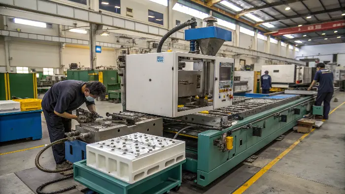
When I work with clients like Jacky, we spend a lot of time on the mold design because it’s the heart of the injection molding process. A good mold design ensures that parts are produced accurately, efficiently, and with minimal defects. It’s a blend of art and science.
Here are some key elements we consider in injection mold design:
- Core and Cavity: These are the two halves of the mold that come together to form the shape of the part. The cavity side usually forms the external surface of the part, while the core side forms the internal features. The precision here is paramount.
- Parting Line: This is the line where the two halves of the mold meet. Its placement is critical for the part’s appearance and for how easily the part can be removed from the mold.
- Runner System: This is the channel that guides the molten plastic from the injection molding machine’s nozzle to the mold cavity. It includes the sprue, runners, and gates. The design of the runner system affects filling pressure, cycle time, and material waste.
- Gating System: The gate is the specific point where the molten plastic enters the cavity. The type, size, and location of the gate are crucial for part quality, affecting things like fill pattern, weld lines, and gate removal.
- Cooling System: Channels are designed within the mold halves to circulate a coolant (usually water). Efficient cooling is vital for controlling the solidification of the plastic and minimizing cycle time. Uniform cooling helps prevent warping and other defects.
- Ejection System: Once the part has cooled and solidified, it needs to be removed from the mold. The ejection system, typically using ejector pins, pushes the part out of the cavity. The design must ensure the part is ejected without damage.
- Draft Angles: These are slight tapers applied to the mold walls, perpendicular to the parting line. They help in easy removal of the part from the mold. My insight highlights this: "ensuring parts易于脱模 (easy to eject)" and "采用拔模斜度以便顺利脱模 (incorporating draft angles for smooth removal)".
- Venting: Small channels are included to allow air trapped in the cavity to escape as the molten plastic fills it. Inadequate venting can lead to incomplete filling or burn marks.
A well-thought-out mold design considers all these aspects to produce high-quality parts consistently and economically. It’s a detailed process that requires experience and a deep understanding of materials and mechanics.
What are the 5 steps of injection molding?
Are you trying to understand the sequence of events in making a plastic part? The injection molding process might seem complex, but it follows a clear, repeatable cycle. Knowing these steps helps in troubleshooting and optimizing production.
The 5 main steps of the injection molding cycle are: 1. Clamping (mold closure), 2. Injection (filling the mold with molten plastic), 3. Dwelling/Cooling (plastic solidifies), 4. Mold Opening, and 5. Ejection (part removal). This cycle repeats for mass production.
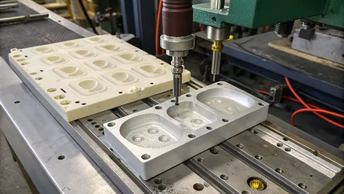
Let’s break down each of these five steps. I’ve seen this cycle countless times on the factory floor, and each step is critical for the final product’s success.
The 5 Key Steps Explained
| Step | Description | Key Considerations |
|---|---|---|
| 1. Clamping | The two halves of the mold are securely closed by the clamping unit of the injection molding machine. | Sufficient clamping force to hold the mold closed against injection pressure. |
| 2. Injection | Molten plastic, prepared in the machine’s barrel, is injected under high pressure into the closed mold. | Injection speed, pressure, and shot size must be precisely controlled. |
| 3. Dwelling & Cooling | After the cavity is filled, pressure is maintained (dwelling/holding phase) to pack out the part. Then, the plastic cools and solidifies, taking the shape of the mold. | Holding pressure, holding time, and cooling time are critical for part quality. |
| 4. Mold Opening | Once the part has solidified, the clamping unit opens the mold halves. | Smooth and controlled opening to prevent damage to the part or mold. |
| 5. Ejection | The solidified part is pushed out of the mold cavity by the ejection system (e.g., ejector pins). | Ejection speed and force must be set to avoid damaging or deforming the part. |
This cycle is the backbone of injection molding. The duration of the cycle, known as the cycle time, directly impacts production efficiency and cost. For someone like Jacky, understanding how part design influences each of these steps is crucial. For example, thicker sections in a part will require longer cooling times, extending the overall cycle. Optimizing each step, even by a few seconds, can lead to significant savings in high-volume production. From my experience, a well-maintained machine and a precisely designed mold are key to a smooth and efficient cycle.
What is injection molding part design for dummies?
New to designing parts for injection molding and feeling a bit lost? It’s common to focus on aesthetics and function, but manufacturability is just as important. Designing without considering molding principles can lead to unmakeable parts or costly revisions.
Injection molding part design for dummies means focusing on fundamental principles like uniform wall thickness, draft angles for easy ejection, rounded corners, and appropriate ribs or bosses for strength, while avoiding undercuts where possible. These ensure the part can be molded efficiently and cost-effectively.
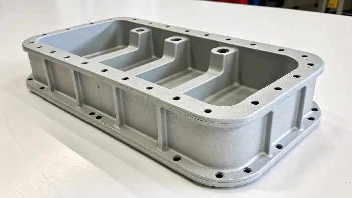
When I started my journey in the mold industry, I quickly learned that a beautiful design on paper doesn’t always translate to a good plastic part. The "for dummies" approach isn’t about oversimplifying, but about focusing on the absolute must-haves for successful molding. My insight emphasizes this: "关键考虑因素包括确保零件易于脱模、保持壁厚均匀、采用拔模斜度以便顺利脱模 (Key considerations include ensuring easy part ejection, maintaining uniform wall thickness, incorporating draft angles for smooth removal)".
Here are some core principles for designing parts for injection molding, explained simply:
- Uniform Wall Thickness: This is probably the most important rule.
- Why? If walls have different thicknesses, the thinner sections cool and shrink faster than thicker sections. This causes warping, sink marks (depressions on the surface opposite thick sections), and internal stresses.
- How? Aim to keep the wall thickness consistent throughout the part. If variations are unavoidable, make the transition gradual.
- Draft Angles: Imagine trying to pull a perfectly straight-sided cup out of a tight-fitting bucket – it gets stuck!
- Why? Draft angles are slight tapers (usually 1-3 degrees) on the walls of the part parallel to the direction of mold opening. They make it easier to eject the part from the mold, reduce friction, and prevent scratches or damage.
- How? Apply draft to all vertical faces. More draft is better, especially for textured surfaces.
- Radii and Rounded Corners: Sharp corners are problematic.
- Why? Molten plastic struggles to flow into sharp corners, leading to incomplete filling. Sharp internal corners also create stress concentrations in the part, making it weaker. In the mold, sharp corners are harder to machine and can wear out faster.
- How? Add generous radii (rounded edges) to both internal and external corners. A good rule of thumb is an inside radius of at least 0.5 times the wall thickness.
- Ribs for Strength: Instead of making the whole part thick for strength, use ribs.
- Why? Ribs add strength and stiffness without significantly increasing wall thickness, which helps avoid sink marks and reduces material usage and cycle time.
- How? Design ribs to be about 50-60% of the main wall thickness to prevent sink marks. Use multiple shorter ribs rather than one very tall one. Ensure they have draft angles too.
- Bosses for Mounting: Bosses are raised cylindrical features used for screws or mounting points.
- Why? They provide attachment points.
- How? Design them with proper wall thickness (similar to ribs, to avoid sink marks) and connect them to the main wall or ribs. Avoid isolated bosses.
- Undercuts – Avoid if Possible: An undercut is a feature that prevents the part from being directly ejected from the mold (e.g., a snap-fit latch).
- Why? They require complex mold mechanisms like side-actions or lifters, which significantly increase mold cost and complexity.
- How? Try to design out undercuts. If unavoidable, discuss with your mold maker early on. Sometimes a simple redesign can eliminate them.
Thinking about these principles from the start, like Jacky does for his consumer electronics components, saves a lot of headaches and money down the line. It’s about designing for the process, not just the product.
Conclusion
Understanding the basics of injection mold design, the molding process itself, and key part design principles is fundamental. From grasping the five steps of molding to applying rules like uniform wall thickness and draft angles, these concepts are crucial for anyone involved in creating plastic parts. This knowledge empowers better design decisions and successful manufacturing outcomes.
