Struggling with inconsistent part quality? Poor mold design choices can lead to costly errors. Discover key considerations for high-performance molds.
Essential considerations for high-performance plastic injection molds include careful material selection, strategic gate location, uniform wall thickness, draft angles, and managing shrinkage. These factors directly impact part quality, production efficiency, and mold longevity, ensuring successful manufacturing outcomes.
You’ve got the basics. But making truly great molds means going deeper. I’ve learned a lot over the years, sometimes the hard way. Let’s explore these critical areas further so you can avoid common pitfalls and master molding right.
How Does Material Selection Fundamentally Impact Your Mold Design?
Choosing the wrong plastic? This decision can derail your entire project. Learn how material properties directly influence mold design and performance.
Material selection critically impacts mold design by dictating shrinkage rates, required steel type, cooling system complexity, and gate/runner design. Each plastic behaves differently, influencing tolerances, surface finish, and overall mold longevity. Proper selection ensures optimal performance.
When I first started in this industry, I underestimated how much material choice affects everything downstream. It’s not just about the final part’s properties; it’s about how the mold itself must be built. For example, some materials like PVC are corrosive. They need corrosion-resistant mold steels, or the mold will degrade quickly. High-temperature plastics, such as PEEK or PPS, require molds built from steels that can handle intense heat cycles without deforming or losing hardness.
Then there’s shrinkage. Every plastic shrinks differently as it cools down from its molten state to room temperature. If you don’t account for this precise shrinkage value in your mold cavity dimensions, your final parts will never meet the required specifications. I remember one project early in my career where we were molding a part from an ABS blend. The initial shrinkage calculation we used was slightly off from the material supplier’s datasheet for that specific grade. The parts came out consistently undersized. We had to remake a significant core insert. It was a costly lesson in double-checking and using exact material data. So, when I approach any new mold design, I always insist on confirming:
- Shrinkage: We need accurate, specific shrinkage data for the chosen plastic grade, both along and across the flow.
- Abrasiveness: Materials filled with glass fibers or other hard minerals are very abrasive. They wear down mold components, especially gates and cavity surfaces, much faster. For these, you’ll need hardened tool steels or special coatings.
- Operating Temperature: Consider the processing temperature of the plastic and the mold steel’s ability to withstand it repeatedly.
- Corrosiveness: As I mentioned with PVC, some plastics release corrosive gases during molding, demanding specific, more expensive mold materials.
Understanding these material-driven aspects from the very start saves an incredible amount of time, money, and headaches later on.Why is Uniform Wall Thickness a Golden Rule in Plastic Part Design?
Seeing ugly sink marks or warped parts? Non-uniform walls are often the culprit. Discover why consistent thickness is key for quality.
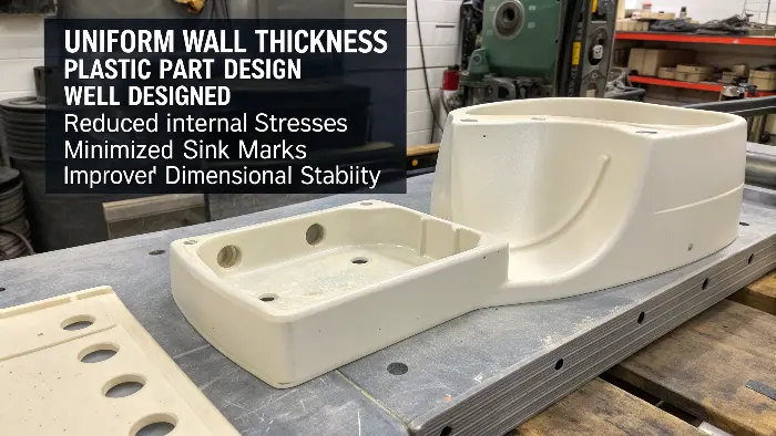
Uniform wall thickness is crucial because it promotes even cooling and plastic flow. This minimizes internal stresses, prevents warping, reduces sink marks, and ensures consistent part strength and dimensional stability. It’s fundamental for good molding.

I often tell designers, "Think like plastic." Molten plastic wants to flow easily through the mold cavity and then cool down as evenly as possible. When you design a part with a thick section right next to a thin one, problems almost always start. The thick section naturally takes much longer to cool and solidify than the adjacent thin section. As that thick area cools, it shrinks more significantly than the already-solidified thin section. This difference in shrinkage, or differential shrinkage, causes internal stresses to build up within the part. These stresses then relieve themselves by causing warpage, where the part twists or bends out of shape. You might also see unsightly sink marks on the surface of the part, directly opposite the overly thick internal section.
One client came to us with a housing design that had a very thick internal boss feature located right next to a relatively thin outer wall. They were experiencing terrible sink marks on the cosmetic surface and the parts were noticeably twisting after ejection. We had to work closely with their design team. The solution was to core out the thick boss, essentially hollowing it, to make its wall thickness consistent with the rest of the part. It solved the sink mark and warpage problems almost immediately. So, when you are designing any plastic part:
- Aim for consistency: Your primary goal should be to keep the wall thickness as uniform as possible throughout the entire part.
- Use ribs for strength: If you need extra stiffness or support in a specific area, use well-designed ribs instead of just thickening the entire wall section. A good rule of thumb is to make the rib thickness at its base about 50-60% of the main wall it’s attached to. This minimizes the risk of sink marks opposite the rib.
- Gradual transitions: If you absolutely must change wall thickness, make the transition between the thin and thick sections as smooth and gradual as you can. Avoid sharp, abrupt changes.
This principle of uniform wall thickness is so fundamental; getting it right is a huge step towards successful injection molding.How Can Strategic Gate Location Make or Break Your Molded Part?
Are your parts showing flow lines or weak spots? Your gate location might be to blame. Learn how placement impacts everything.
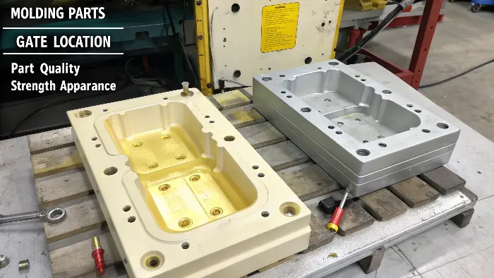
Strategic gate location is vital as it controls how molten plastic fills the mold cavity. Proper placement ensures complete filling, minimizes cosmetic defects like flow lines and weld lines, and can optimize part strength and reduce warpage.

The gate is the small opening through which the molten plastic enters the actual part cavity. Its location might seem like a minor detail in the grand scheme of a complex mold, but it’s incredibly powerful and has a huge influence on the final part. I’ve personally seen projects succeed or fail based almost purely on the choice of gate location and type. Think of it as the starting line and the path for a race. You want the plastic to flow smoothly, fill the entire cavity completely, and do so in a way that optimizes the part’s properties.
A poorly placed or poorly designed gate can cause a host of problems:
- Cosmetic defects: "Jetting" can occur if the plastic shoots across the cavity like a stream instead of flowing smoothly, leaving a squiggly mark. Flow lines or blush marks can appear if the plastic hesitates or impinges directly onto an opposite core surface.
- Structural issues: Weld lines, also known as knit lines, form where two or more flow fronts meet. If these occur in structurally critical areas of the part, they can create significant weak points.
- Warpage: An unbalanced filling pattern, where one part of the cavity fills much faster or under different pressure than another, can lead to uneven shrinkage and internal stresses, resulting in warpage.
I remember a project involving a long, thin part we were molding. The initial design had a single gate at one end. The plastic had to travel a very long distance. By the time it reached the far end of the cavity, it had cooled too much, leading to short shots (incomplete parts) and high internal stress. We modified the mold to add a second gate near the other end, effectively turning it into a multi-gate system with a more balanced fill. The problems vanished, and part quality improved dramatically.
When I’m deciding on gate location with my team, we always consider: - Material type: Different plastics have different flow characteristics. Some are very shear-sensitive.
- Part geometry: We try to gate into the thickest section of the part if possible, as this helps with packing out the part during the holding phase to compensate for shrinkage.
- Cosmetic requirements: Gates should ideally be placed on non-critical or hidden surfaces, or in locations where they can be easily and cleanly trimmed without affecting the part’s appearance or function.
- Filling pattern: We often use mold flow simulation software to predict how the plastic will fill the cavity based on different gate locations. This helps us identify potential problems before any steel is cut.
Choosing the right gate location is truly a balance of engineering science and practical experience.What’s the Best Way to Prevent Unsightly Sink Marks in Your Parts?
Tired of those annoying depressions on your parts? Sink marks can ruin aesthetics and function. Let’s tackle how to prevent them.
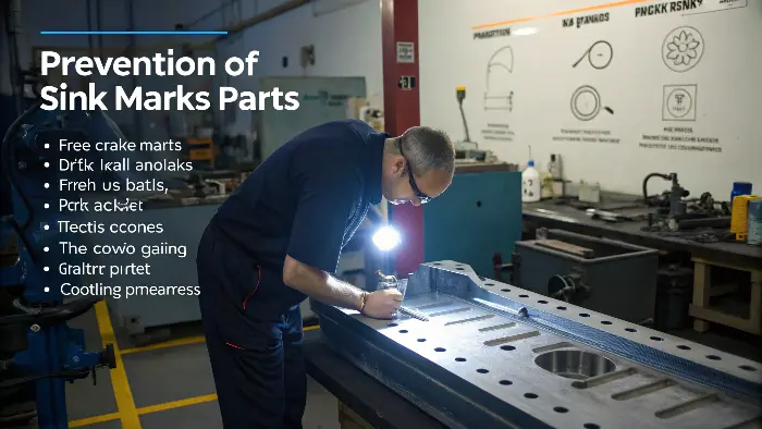
Preventing sink marks involves designing parts with uniform wall thickness, coring out thick sections, optimizing gate location and size for proper packing, and ensuring adequate cooling. Material choice and processing parameters also play a crucial role.

Sink marks are definitely one of the most common and frustrating defects we encounter in injection molding. They appear as depressions or shallow craters on the surface of a molded part. They typically occur on the surface opposite thicker sections within the part, such as areas where ribs, bosses, or screw studs are located. The mechanism is straightforward: as the molten plastic cools and solidifies inside the mold, it shrinks. If an area of the part is significantly thicker than the surrounding areas, its core will remain molten longer than its outer surface. As this inner core finally cools and shrinks, it pulls the already solidified (or semi-solidified) outer surface inward, creating the visible sink.
I’ve battled sink marks on countless projects throughout my career. The key to winning this battle is a multi-pronged attack, starting with the part design itself. As we’ve already discussed, maintaining uniform wall thickness is your absolute best friend in preventing sinks. If you need to incorporate features like ribs or bosses, you must design them carefully:
- Rib thickness: A common design guideline is to keep the thickness of a rib at its base to about 50-60% of the nominal wall thickness it is attached to. Any thicker, and you risk a sink mark on the opposite surface.
- Boss design: Avoid designing solid, thick bosses. Instead, core them out from the bottom or sides to maintain a consistent wall thickness that matches the rest of the part.
Second, mold design features also play a critical role: - Gate location and size: Locating the gate near potentially problematic thick sections can allow for better packing pressure to be applied to that area, helping to force more material in to compensate for shrinkage. The gate also needs to be large enough not to freeze off before packing is complete.
- Cooling: Ensure efficient and targeted cooling in the mold around areas prone to sink marks. More cooling can help the thick section solidify faster and more uniformly.
Third, the actual injection molding processing conditions are critical: - Packing pressure and time: Applying sufficient packing pressure for an adequate amount of time helps push more molten plastic into the cavity as the material begins to shrink.
- Melt temperature: An excessively high melt temperature can lead to increased overall shrinkage, making sink marks more likely or more severe.
I recall a project for a consumer electronic device that had a beautiful, high-gloss exterior finish requirement. Even the tiniest sink marks were completely unacceptable. We spent a lot of time with the client iterating on the part design, specifically optimizing the intersections of ribs and walls, and then on our side, we meticulously fine-tuned the packing pressure profile and cooling times on the molding machine. It’s always a combination of good, thoughtful design upfront and smart, careful processing during production.How Can Proper Shut-Off Angles Save Your Mold and Prevent Flash?
Dealing with flash on your molded parts? Poor shut-off design could be the cause. Learn why this detail is critical for mold integrity.
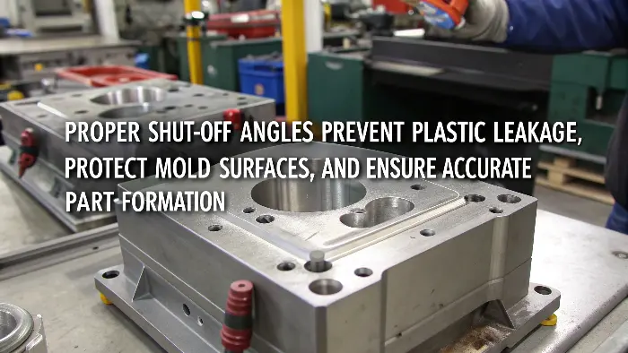
Proper shut-off angles ensure a tight seal between mold halves or moving components like slides. This prevents plastic leakage (flash), protects mold surfaces from damage, and ensures accurate part formation. Typically, 3-5 degrees is recommended.

Shut-off, in mold making, refers to the area where two distinct parts of the mold meet to form a seal, preventing molten plastic from escaping the cavity. Think of a window closing tightly against its frame – you want a perfect, gap-free fit. If these shut-off surfaces aren’t designed correctly with appropriate angles, or if they wear down over many cycles of opening and closing, the high-pressure molten plastic can find a way to sneak through the tiny gaps. This results in a thin film of unwanted plastic attached to the part, which we call "flash." Flash is not just an aesthetic issue; it often requires manual trimming, adding to labor costs and production time. Even worse, repeated flashing, where plastic is forced between the shut-off surfaces, can erode or damage the precision-machined mold surfaces themselves. This is often called "coining" or "hobbing" and can lead to very expensive mold repairs.
I’ve seen molds, especially those with complex internal features created by slides or lifters, where designers initially overlooked the importance of adequate shut-off angles. They might have designed these mating surfaces as straight, 90-degree (or "line-to-line") contacts. These types of shut-offs wear down relatively quickly, and soon enough, flash starts appearing. Incorporating a small angle, usually a minimum of 3 to 5 degrees, on these mating surfaces helps create a much more robust and durable seal. This angle acts like a wedge, ensuring a tight, positive seal even with slight wear over the lifetime of the mold. It’s a self-sealing mechanism.
When my team designs shut-off areas, we pay close attention to these points:
- Minimum angle: While 3 degrees is often cited as a common minimum, I always push for 5 degrees or even more if the design allows, especially if we’re dealing with abrasive materials (like glass-filled plastics) or expect a very long production run for the mold.
- Surface finish: A smooth, well-polished surface finish on the shut-off areas significantly improves their sealing capability.
- Steel hardness and type: Using harder, more wear-resistant tool steels for components with shut-off features helps maintain their integrity for longer.
- Venting considerations: It’s important to ensure that the design of shut-offs doesn’t inadvertently block or compromise essential parting line vents, which are needed to allow air to escape the cavity.
I remember one instance where we were troubleshooting a complex mold with multiple side-actions (slides). The original shut-offs for these slides were designed with very shallow angles, less than 2 degrees. After just a few thousand production shots, flash started appearing consistently around the areas where the slides met the main cavity. We had to pull the mold from production, take it to the toolroom, and re-machine the shut-off surfaces on the slides and their corresponding pockets with steeper, more robust angles (around 5 degrees). That solved the flashing issue permanently. It’s a small detail in the overall mold design, but one that really protects your significant investment in the tooling.Conclusion
Mastering these design considerations transforms your approach. Better material choice, gate placement, wall uniformity, sink prevention, and shut-offs lead to high-performance molds and superior parts.
