Have you ever created a plastic part that was absolutely perfect on screen, then encountered infinite difficulty during production? A minor mistake in how the part is being molded can result in expensive tooling changes and annoying delays. Learning about the fundamental elements of an injection mold is the first step towards closing the gap between design and perfect production, so that your vision comes true without the hassles.
The flow of an injection mold has seven fundamental components, namely, the molding parts (cavity and core), the runner system, the guiding mechanism, the ejection system, the side parting and core-pulling mechanism, the cooling and heating system and the venting mechanism. All these systems actually have a designated task. All of them have to interact perfectly to shape the molten plastic, then cool the part and successfully remove the completed piece of the mold.
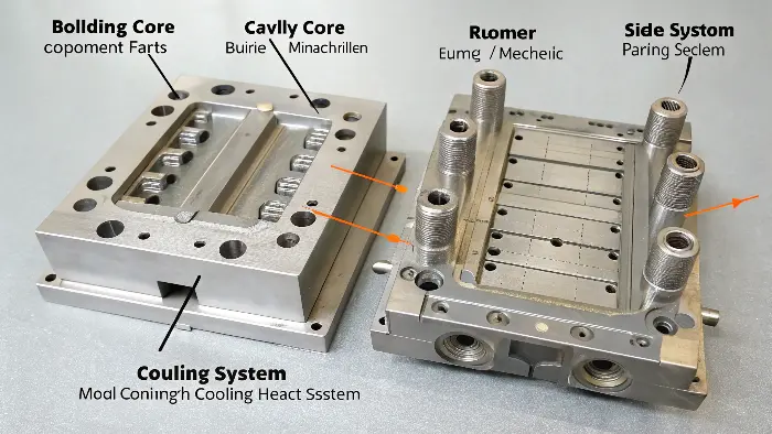
In order to really get a grip on this we must have a closer look at each system. My career has been in these parts and I can tell you that nothing could be more important than knowing these parts in and out as a good designer can be transformed into a great designer. It is the secret of successful communication with your manufacturing partners and being able to predict problems before they bring you time and money losses. Ok, let us take a dip and see how it all comes together.
What is the basic of injection molding?
You hear the term "injection molding" all the time around our company, but can you honestly say you can explain the fundamental process from start to finish? Not knowing this can make it overwhelming to have technical discussions with toolmakers and can lead to simple misunderstandings of design limitations. Let’s do a quick refresher of the fundamentals so you have a good grasp for every design decision you make.
In essence, the process of injection molding is a production process for producing parts through the injection of molten material into a mold. The process starts when plastic pellets are melted and then injected under high pressure into a specially designed mold cavity. The plastic solidify and harden in the shape of the cavity in the mold. Later, the mold opens and the completed part is pushed out. The process is very repeatable and very efficient in producing in large numbers.
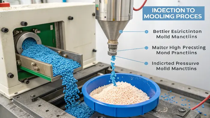
In order to comprehend the process, you must know how a string of events occur within the few blinks of an eye. I recall the initial occasion I was on a factory hallways and yes, observed a machine making parts. It seemed almost magical but it was soon discovered that each and every step is regulated engineering masterpiece. The slightest variation of a half of a second in one part may give a totally different ending part. All of this is referred to as the injection molding cycle.
The Injection Molding Cycle
The process is a loop, repeating over and over to produce thousands or even millions of identical parts. It can be broken down into a few key stages.
| Stage | Action | Purpose |
|---|---|---|
| 1. Clamping | The two halves of the mold are pressed together by the clamping unit of the machine. | To hold the mold securely shut against the high pressure of the injected plastic. |
| 2. Injection | Molten plastic is forced from the injection unit into the mold. | To fill the cavity of the mold completely with material. |
| 3. Dwelling (Packing) | After the cavity is filled, more pressure is applied for a short time. | To pack more material into the cavity to compensate for shrinkage as the plastic cools. |
| 4. Cooling | The part is left to cool and solidify inside the mold. | To allow the part to become solid enough to be ejected without deforming. This is often the longest part of the cycle. |
| 5. Mold Opening | The clamping unit pulls the two halves of the mold apart. | To create space to remove the finished part. |
| 6. Ejection | The ejection system pushes the solidified part out of the mold. | To release the finished part from the mold core. |
Understanding this cycle is crucial for a designer. For example, if you design a part with very thick walls, the cooling time will increase significantly. This makes the cycle time longer and the cost per part higher. Thinking about each of these stages as you design will make you a much more effective partner in the manufacturing process.
What are the main elements of a mold?
You’ve completed your product design, and it’s wonderful. But now you need to think about the sophisticated tool that will make it. A mold is more than a plain old block of steel with a hole drilled in it. Misperceiving its sophisticated internal systems can result in design errors, such as sink marks or warping, that cost an enormous amount of money and time to correct once the steel is cut. Let’s discuss the seven fundamental components that constitute almost every injection mold.
The seven principal elements of an injection mold are the molding elements (cavity and core), the runner system, the guide system, the ejection system, the side parting/core-pulling system, the cooling/heating system, and the venting system. Together, they create the plastic, guide the mold halves, eject the part, create complex features, control the temperature, and create a path for air escape.
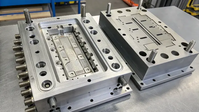
Being a founder of my own mold and CNC trading company, I personally experienced how the negligence regarding such factors put my clients in troubles. A designer might specify something that needed a complicated side-action mechanism, where he had not considered the additional expense or the scar, which would be left on the piece. A technique by which I can do that is by gaining an understanding of what all of these seven systems do so that I can design parts not only in an effective way, but more importantly in an efficient and high quality way during the manufacturing process.
The 7 Core Systems of an Injection Mold
Think of these as the vital organs of the mold. If any one of them isn’t working correctly, the whole process fails.
| System | Primary Function | Primary Components |
|---|---|---|
| 1. Molding Parts | Gives the final shape to the plastic part. | Cavity (gives the outer surface shape), Core (gives the inner surface shape). |
| 2. Runner System | It offers a path through which molten plastic can flow from the machine to the cavity. | Sprue, Runners, Gates. |
| 3. Guiding Mechanism | Ensures that the two halves of the mold fit perfectly each time. | Guide Pins, Guide Bushings. |
| 4. Ejection System | Pushes the finished part out of the mold after cooling. | Ejector Pins, Ejector Plate, Return Pins. |
| 5. Side Parting & Core-Pulling | Produces thin details such as undercuts or side holes. | Lifters, Sliders (or Slides). |
| 6. Cooling & Heating System | Regulates the mold temperature for plastic solidification. | Cooling Channels, Hoses, Temperature Controller. |
| 7. Venting System | Allows air within the cavity to escape as plastic enters. | Vents (tiny holes), Parting Line Gaps. |
Let’s take a closer examination of each one. The Molding Parts, the core and cavity, are the focal point of the mold. They are precision-machined to be the negative of your part. The Runner System is the circulatory system, delivering the lifeblood—molten plastic—to the cavity. The Guiding Mechanism is the skeleton, providing alignment and stability. The Ejection System is like the muscles, pushing the part out. For complex parts with features like clips or holes on the side, the Side Parting & Core-Pulling System uses moving parts called sliders and lifters to form those features and then move aside so the part can be pushed out. The Cooling System is crucial to manage the cycle time and part quality. Finally, the Venting System is the behind-the-scenes hero. Without it, air would get trapped and result in incomplete parts or burn marks.
What are the components of an injection molding press?
It is simple to mix up the mold with the large machine it resides in. This can make technical conversations when talking to factory personnel confusing and could be an indication of a lack of your hands-on knowledge. This can sometimes make your authority as a designer questionable when negotiating manufacturing feasibility. So, let’s clearly differentiate the mold from the injection molding press and take a look at the machine’s significant components.
A machine or press, called an injection molding press, has three essential components: the injection unit, the clamping unit, and the control unit. The injection unit melts and injects the plastic. The clamping unit maintains the mold closed during injection and opens it during part ejection. The control unit is the thinking component of the process, manipulating all the critical parameters like pressure, temperature, and timing.
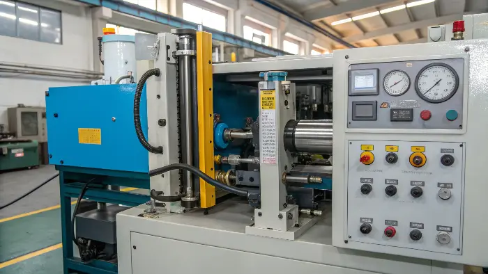
I spoke a lot about such units when I was assisting one of my clients in finding a new machine to place on their factory. They were doing a component of very thin wall thickness and hence needed an injection unit which could have very high speeds and pressures. Additionally, the area of the part was also large, hence they required a force (tonnage) sufficient clamping unit to ensure that they maintained the mold without flashing. It is equally important to understand such components of the machine as the mold.
A Closer Look at the Machine
The press is the powerhouse that makes everything happen. Let’s break down its three main sections.
The Injection Unit
This is where the process begins. Its job is to prepare the plastic and force it into the mold.
- Hopper: A large funnel that holds the raw plastic pellets and feeds them into the barrel.
- Barrel: A heated cylinder where the plastic pellets are melted and conveyed forward.
- Reciprocating Screw: This is the key component inside the barrel. It rotates to move the pellets forward, melt them through friction and heat, and mix them into a consistent molten state. It also acts like a plunger, moving forward to inject the molten plastic into the mold.
- Nozzle: The exit point of the barrel that presses up against the mold’s sprue bushing to deliver the plastic.
The Clamping Unit
This is the powerful section of the machine that handles the mold.
- Platens: There are two main platens: a fixed platen (where the cavity half of the mold is mounted) and a moving platen (where the core half is mounted).
- Tie Bars: Four large steel rods that connect the ends of the clamping unit and guide the moving platen. The distance between the tie bars determines the maximum size of the mold the machine can hold.
- Clamping Mechanism: This is the system (usually hydraulic or all-electric) that moves the platen and generates the massive force needed to keep the mold closed during injection. This force is known as tonnage.
The Control Unit
This is the brain of the entire machine, usually a sophisticated computer or PLC (Programmable Logic Controller). The operator uses this interface to set, monitor, and adjust every variable of the process, including temperatures, pressures, speeds, and times for every stage of the cycle. Modern control units allow for incredible precision, which is essential for high-quality, consistent production.
The Injection Unit
This is where the process begins. Its purpose is to condition the plastic and force it into the mold.
- Hopper: A big funnel that holds the plastic raw pellets and feeds them into the barrel.
- Barrel: A cylinder that is heated in which the plastic pellets are melted and pushed forward.
- Reciprocating Screw: This is the most crucial equipment inside the barrel. It rotates to drive the pellets forward, melt them due to friction and heat, and mix them to a homogenous molten state. It also works like a plunger, thrusting forward to drive the molten plastic into the mold.
- Nozzle: Where the barrel presses against the sprue bushing of the mold in a bid to force the plastic out.
The Clamping Unit
This is the powerful section of the machine that handles the mold.
- Platens: Two platens are of special significance: a stationary platen (which accommodates the cavity half of the mold) and a moving platen (which accommodates the core half).
- Tie Bars: Four big steel tie bars connect the clamping unit ends and support the traveling platen. The travel between the tie bars will dictate the mold size that the machine can handle.
- Clamping Mechanism: The (usually hydraulic or all-electric) press that powers the platen and applies the enormous pressure necessary to keep the mold shut during injection. This is known as tonnage.
The Control Unit
It is the mind of the machine, typically an advanced computer or Programmable Logic Controller. It is by this interface that the operator gives input to establish, observe, and regulate each process variable, i.e., temperatures, pressures, rates, and timing for every cycle stage. Advanced control units enable phenomenal precision, which is highly required for high-quality, uniform output.
What are the components of injection molding?
We’ve looked at the mold and the press as standalone systems. But how do they function together as part of the big picture of manufacturing? If you consider them as standalone systems, it will make you lose the entire process. That prevents you from being able to actually design for manufacturability. So let’s put it all together and consider the mold, the machine, and the material as one system.
The three major components of the entire injection molding process are the injection molding machine (the press), the injection mold (the tooling), and raw plastic material (the resin). The machine provides the force, motion, and control. The mold provides the accurate shape. The material is the material being transformed into the finished part. A successful outcome depends only on the perfect interaction of these three major components.
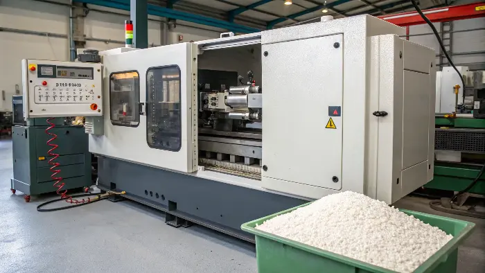
This is what I aim at teaching in CKMOLD. It is a three legged stool. In case either leg is weak the entire thing collapses. You may have the finest machine and the finest material, yet with a poorly designed mold, you are going to have bad parts. Similarly, perfect mould in machine that is not adjusted to take specific material will also fail. As a model designer such as Jacky you can exercise most control of the mold design, however the other two component will have to be taken into account to be a success.
The Interplay of Machine, Mold, and Material
Thinking about how these three elements interact is the key to Design for Manufacturing (DFM). Your design choices directly impact all three. For example, if you design a very large part, you are immediately dictating the need for a large-tonnage machine and a large, expensive mold. Let’s look at how a designer should think about this relationship.
| Component | Role in the Process | Key Considerations for a Designer |
|---|---|---|
| Machine (Press) | Provides the power, control, and physical motion to operate the mold and process the material. | Tonnage: Does my part’s surface area require a high clamping force? Shot Size: Can the machine inject enough plastic for my part’s volume? Platen Size: Will my mold physically fit in the machine? |
| Mold (Tooling) | Contains the custom-machined cavity that gives the plastic its final shape. | Draft Angles: Have I added enough taper for the part to eject easily? Wall Thickness: Is it uniform to prevent sink and warp? Gate Location: Where will the plastic enter, and will it leave a mark? Venting: Is there a way for air to escape? |
| Material (Resin) | The raw thermoplastic or thermoset that is melted and formed into the part. | Shrinkage Rate: How much will the material shrink as it cools? This must be built into the mold design. Flow Characteristics: Is it easy-flowing (like nylon) or stiff (like polycarbonate)? This affects wall thickness and gate design. Aesthetics: Does it need to be clear, colored, or textured? |
I was part of a project of one of the consumer electronics devices. The designer as well as Jacky had done very well in creating a very beautiful housing characterized by a high-gloss covering, and this was done of ABS plastic. Yet on a note visible surface was put the gate. The gate mark was not acceptable when the first parts were released. We were required to collaborate and reengineer the system of the mold of the runner in order to utilize an alternative form of gate, which was in a discreet space. The entire part needed a little modification, but such planning would have avoided an awful lot of headache had we considered the mold and the material right in the beginning.
Conclusion
Finally, learning the seven main elements of a injection mold is the key of anybody who is serious about designing and producing products. It is also essential to know the interaction of the molding parts, runner, guiding, ejection, cooling, venting and side-action systems. In combined with the concept of the press and the material, you give yourself the power to produce more superior, efficient and cost effective products. This alone is the secret of doing molding right.
FAQs
1. What are the primary elements of an injection mold?
An injection mold is made up of a number of main components: mold base (plates or frame), core, cavity, sprue bushing/nozzle, runner system (runner, runners, and gates), ejector pins, cooling channels, venting, and alignment devices like guide pins and interlocks.
All these components act together to offer efficient mold filling, part formation, and ejection. A good mold enhances product quality, reduces defects, and maximizes cycle time in manufacturing.
2. How do the core and the cavity differ?
Cavity creates the outer form of a piece of work and also tends to develop in the stationary half of a mould. The core creates inner details such as a hole or a recess and tends to be located in the moving half.
They operate in combination to produce the entire geometry of the part. Proper cavity and core design is needed for achieving repeatable dimensions and quality surface finishes.
3. Why are cooling channels necessary?
Cooling channels (conformal cooling) regulate mold temperature for quick, uniform cooling. Minimizing cycle time and warping or defects, they’re essential to high-accuracy molding.
Inadequate cooling design may result in uneven shrinkage, longer production time, and increased rejection. Sufficient cooling also results in better dimensional stability of the moulded product.
4. What are ejector pins and how do they work?
Ejector pins are metal strips that force the cooled plastic component out of the mold. The right positioning and number are necessary to prevent warping of fragile details and provide even ejection pressure.
Incorrect ejection can cause part damage or markings. Certain intricate molds also make use of ejector sleeves, blades, or plates to deal with certain shapes.
5. What is mold alignment and interlock?
Alignment components consist of guide pillars/bushings to guide accurately and interlocks (pins, grooves, slots) to avoid misalignment. The features avoid flash, warpage, and dimensions errors. Appropriate alignment is required for multi-cavity molds to make parts of the same quality. Alignment reduces mold parts wear and optimizes tool life.
6. How are injection molds made?
Injection molds are made by machining. 5-axis machining is the most popular method since it can produce complex contours and can reach hard-to-access regions in molds. Post-machining, surface finishing techniques such as grinding and polishing can be employed to attain the necessary smoothness of the cavity surfaces.
7. What are the key design parameters for injection mold design?
Injection mold design is a complex process involving a lot of considerations. Major design decisions in injection mold design are the choice of materials, design of gate and runner, draft angles, wall thickness-to-depth ratios, tolerancing, and sink mark and parting line positions.
8. What types of materials are used to make injection molds?
Depending on the process parameters such as volume and pressure, molds are typically produced with steel alloys or aluminum alloys. For lower-intensity tasks, the material selection can involve various plastics, resins, and rubbers.
