Have you ever designed a plastic part that looked perfect on screen, only to see it fail in production with warpage or sink marks? These issues lead to expensive tool modifications, project delays, and unhappy clients. What if you could predict and solve these manufacturing defects before a single piece of steel is cut? Mold flow analysis is the crystal ball you need to ensure your design succeeds from the very first shot.
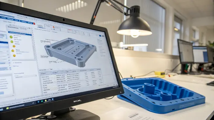
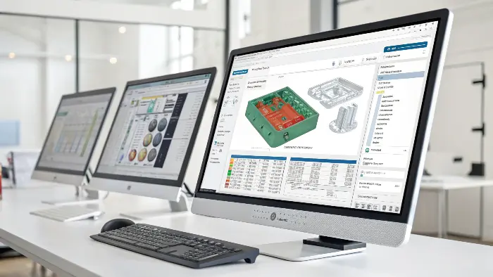
Mold flow analysis is a powerful software simulation that shows how melted plastic resin flows to fill an injection mold. By visualizing this process, designers can optimize gate locations, predict where weld lines will form, and identify hard-to-fill areas. This foresight allows you to prevent critical defects like warpage, sink marks, and short shots before the mold is even built, saving enormous amounts of time and money and ensuring a high-quality final product.

It sounds like a superpower for designers, right? Being able to see the future of your part and fix problems before they happen is a game-changer. But to really harness this power, we need to break it down into its core components. It all starts with the most fundamental part of the process: the filling analysis. Let’s dive into what that really means and how it forms the backbone of the entire simulation. Understanding this first step is key to unlocking all the other insights mold flow has to offer.
What is a mold filling analysis?
You’ve carefully placed the gate on your new part design, confident it’s in the optimal spot. But when the first parts come out of the machine, you see incomplete sections or ugly flow marks. Now you’re facing a difficult choice: pay for expensive modifications to the steel mold or try to tweak machine settings, hoping for a fix that might compromise the part’s integrity. A mold filling analysis lets you avoid this gamble entirely.
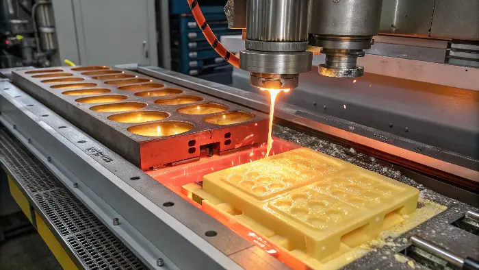
A mold filling analysis is a specific simulation within the broader mold flow process that focuses purely on the injection or "filling" phase. It creates a visual animation of how the molten plastic travels through the runner system, enters through the gates, and fills the mold cavity. Its primary goal is to confirm that the cavity will fill completely and uniformly, allowing you to spot potential issues like short shots, air traps, and the exact location of weld lines.

A filling analysis is the first and most fundamental check you should perform. It answers the simple question: "Can we even make this part?" I’ve seen many projects where this basic step was overlooked, leading to major problems down the line.
The Core Objectives of Filling Analysis
The main goal is to achieve what we call a "balanced fill." This means the plastic reaches the end of all its flow paths at the same time and under similar pressure. If one part of the mold fills much faster than another, it creates uneven pressure and packing, which is a primary cause of warpage. The analysis also highlights areas of "hesitation," where the flow front slows down dramatically. This can cause surface defects and stress marks on the final part.
Visualizing the Flow Front
The result you’ll look at most is a color-coded animation showing the plastic flow over time. It looks like a weather map, but for plastic. This visual is incredibly powerful. It shows you exactly where two or more flow fronts will meet, creating a weld line. While unavoidable in many designs, the analysis lets you position gates to move these weld lines to non-critical or non-visible areas. It also shows you where air will be pushed and trapped, allowing you to add vents to the mold design to prevent burn marks or incomplete filling. I remember a project for a complex speaker grille. Our initial design showed a massive, weak weld line right down the middle. By simply adding a second gate, the filling analysis confirmed we could move the weld lines to hidden areas, saving us a huge headache.
What are the parameters of mold flow?
You run a mold flow analysis, but the results don’t match what’s happening on the factory floor. The simulation looks perfect, but the real parts are still warping out of shape. This makes you question the value of the software itself. If your inputs are wrong, the output is useless, and you’ve just wasted time and resources on a misleading report. The accuracy of your analysis depends entirely on the quality of your inputs.
The accuracy of a mold flow analysis hinges on three main categories of parameters. First is the Material Properties, including the specific plastic’s viscosity, thermal data, and PVT (Pressure-Volume-Temperature) characteristics. Second are the Process Settings, which mimic the real-world machine settings like melt temperature, mold temperature, and injection speed. Third is the Geometry, which is the 3D CAD model of the part, runners, and cooling channels. Getting these three right is essential for a reliable result.

There’s a saying in the world of simulation: "Garbage in, garbage out." This could not be more true for mold flow analysis. The simulation is only as smart as the data you feed it. Early in my career, I spent days trying to solve a warpage issue that the analysis didn’t predict. It turned out the engineer running the simulation had used a generic "Polypropylene" setting from the software’s library. The problem was, there are thousands of grades of polypropylene! Once we got the exact technical datasheet from the material supplier and input the correct PVT data for that specific grade, the simulation perfectly matched the real-world warpage. It was a powerful lesson: the details matter more than anything.
The Three Pillars of Mold Flow Parameters
To get a reliable analysis, you have to be precise with your inputs across these three areas. A mistake in any one of them can throw off the entire prediction.
| Parameter Category | Key Inputs | Why It’s Critical |
|---|---|---|
| Material Data | Viscosity curves, PVT data, Specific Heat, Thermal Conductivity | This data determines exactly how the plastic will flow, shrink, and cool. Using a generic material profile instead of the specific grade you plan to use is the most common mistake and leads to wildly inaccurate predictions. |
| Process Settings | Melt Temperature, Mold Temperature, Injection Time, Packing Profile | These settings simulate the actual injection molding machine. They must be realistic for the chosen material and the machine’s capabilities. An unrealistic injection time, for example, can hide potential filling problems. |
| Geometric Model | Part geometry, Runner/Gate design, Cooling channels | This defines the physical space the plastic fills and cools in. The quality of the 3D mesh is vital. A poor-quality mesh can cause calculation errors, especially around small features or sharp corners. |
How to read a mold flow analysis report?
You’ve just received a 50-page mold flow report. It’s filled with colorful plots, complex graphs, and technical jargon that feels overwhelming. You’re not sure what to focus on, and you’re worried you might miss a critical warning sign hidden in the data. This can lead to the very production problems you were trying to avoid, making the report useless if you can’t interpret it correctly. The secret is knowing which key results to look for.
To read a mold flow report effectively, focus on five key result plots. Look at the Fill Time to ensure the part fills smoothly. Check the Pressure at End of Fill to see if it’s within the machine’s limits. Examine the Weld Lines plot to identify potential weak spots. Pinpoint Air Traps where voids or burn marks could form. Finally, analyze the Warpage plot to predict how the part will deform after cooling. These five plots give you the most critical information.

Think of yourself as a detective looking for clues. You don’t need to understand every single data point on every page. You need to know where to look for the "smoking guns" that point to potential trouble. Over the years, I’ve learned to zero in on a few key visuals that tell me 90% of the story.
Decoding the Visuals
Let’s break down what to look for in these key plots.
- Fill Time Plot: You want to see smooth, even color bands spreading across the part, like a smooth, rising tide. If you see large areas where the color bands are compressed or jagged, it means the plastic flow is hesitating or stalling, which can cause surface defects.
- Pressure at End of Fill Plot: This tells you how hard the machine has to work to fill the part. As a rule of thumb, I aim to keep the injection pressure below 80% of the machine’s maximum capacity. If the analysis shows the pressure is spiking near the limit, you have a problem. You’ll need to improve the flow path, perhaps with a larger gate or thicker walls.
Beyond Filling: Cooling and Warping
The analysis doesn’t stop once the part is full. The cooling and warpage results are where you find the problems that affect final part quality and dimensions.
- Temperature at End of Cooling Plot: This plot is crucial for both cycle time and quality. Look for "hot spots"—areas that are significantly hotter than the rest of the part when it’s ejected. Uneven cooling is the number one cause of warpage. If you see a hot spot, you know you need to add more cooling channels in the mold in that specific area.
- Warpage Plot: This is the moment of truth. The software will show you a simulated version of your final part, with any distortion or bending exaggerated for clarity. It tells you not just if the part will warp, but how it will warp. Your job is to analyze the result and figure out why it’s warping—is it due to uneven cooling, variations in wall thickness, or material shrinkage? Then, you can go back and fix the root cause in your design.
What is the best software for mold flow analysis?
You’re convinced that you need to start using mold flow analysis, but a quick search reveals dozens of software options. They range from free plugins integrated into your CAD software to incredibly expensive, standalone enterprise suites. Choosing the wrong one could mean wasting money on features you don’t need or, worse, getting inaccurate results from a tool that isn’t robust enough for your complex projects. This paralysis of choice is a real problem for many designers.
There isn’t one single "best" software for everyone, but the undisputed industry leader is Autodesk Moldflow. It is renowned for its comprehensive features and the most extensive and accurate material database available. Other top contenders include Moldex3D, which is praised for its advanced 3D meshing and high-fidelity results, and SOLIDWORKS Plastics, which is an excellent choice for designers already working within the SOLIDWORKS ecosystem. The best choice ultimately depends on your budget, existing workflow, and project complexity.

Choosing the right tool is a balance between power, usability, and cost. I’ve used several different packages throughout my career, and each has its place. The key is to match the tool to the job at hand.
The Industry Giants
- Autodesk Moldflow: This is the gold standard that most of the industry uses. I’ve personally used it on countless projects. Its biggest advantage is its material database. Autodesk works directly with material suppliers to get incredibly accurate data, which, as we’ve discussed, is the most critical input for a reliable analysis. It comes in different tiers, like Moldflow Adviser for designers who need quick checks and Moldflow Insight for expert analysts doing deep-dive simulations.
- Moldex3D: This is a very powerful and respected competitor. I’ve seen colleagues achieve amazing results with it. Its main claim to fame is its true 3D analysis engine, which can provide more accurate results for very thick, complex parts with intricate geometry. It can have a steeper learning curve, but for certain applications, its precision is unmatched.
Integrated vs. Standalone
- SOLIDWORKS Plastics: If your entire design team lives and breathes SOLIDWORKS, this is a fantastic option. Because it’s integrated directly into the CAD interface, you don’t have to waste time exporting and importing models. It’s perfect for designers who want to run quick, early-stage analyses to check for obvious problems. For the most complex and critical projects, many teams will still export the final design to a specialist tool like Moldflow for the final verification.
Here is a simple breakdown to help you choose:
| Software | Best For | Key Strength |
|---|---|---|
| Autodesk Moldflow | High-accuracy analysis, industry-wide compatibility | Unmatched material database, robust and trusted solver |
| Moldex3D | Very complex 3D parts, high-fidelity simulation | Advanced 3D meshing and analysis capabilities |
| SOLIDWORKS Plastics | Designers in the SOLIDWORKS ecosystem, early-stage checks | Seamless CAD integration and ease of use |
Conclusion
Mold flow analysis is not just a piece of software; it’s a vital design philosophy that bridges the gap between your digital model and the physical world. It empowers you to digitally predict and solve manufacturing issues before they become costly, time-consuming physical problems. By understanding the key parameters, learning how to read the reports, and choosing the right tool for your needs, you can elevate your designs from guesswork to data-driven certainty.
