
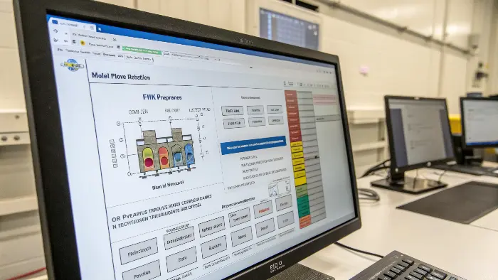
Quick answer: Mold-flow validation compares predicted relationships with controlled T1 evidence; it is not a demand that every plotted number match exactly. Freeze the model and trial conditions, collect comparable fill, pressure, temperature and dimensional data, explain differences, and update tooling decisions or model assumptions through a traceable correlation record.
Release Decision Matrix
| Prediction | T1 evidence | Useful comparison |
|---|---|---|
| Fill progression | Sequenced short shots or controlled fill percentages | Feature and cavity fill order |
| Pressure demand | Machine trace and cavity pressure where available | Curve shape, transfer behavior and reserve |
| Thermal pattern | Calibrated surface or in-tool temperature evidence | Hot and cold regions under stable cycles |
| Warpage direction | Datum-based metrology after defined conditioning | Mode, direction and relative magnitude |
Approval Checklist
- Archive the pre-T1 model, material data, inputs, plots and limitations.
- Record actual resin condition, machine, temperatures, settings and thermal state.
- Label all parts by cavity, process condition and sequence.
- Compare fill order using controlled short shots.
- Compare pressure curve events using equivalent measurement definitions.
- Map predicted welds and air traps to visual and functional evidence.
- Measure temperature and warpage with documented methods and datums.
- Classify discrepancies, assign actions and retain the correlation record.
Freeze the Prediction Package Before T1
Archive CAD revision, mesh, material dataset, gate and runner model, cooling layout, machine assumptions and process inputs. Export plots and key values with units and scale. If the model changes after seeing the parts, retain both versions; otherwise the project cannot distinguish prediction from hindsight.
State limitations. A filling analysis may not support shrinkage or cooling conclusions, and a generic material dataset may only support relative comparison. Validation should test claims the model actually made.
Make the Trial Comparable
Use the intended resin grade and record lot, drying, color, regrind and moisture condition. Verify actual melt and cavity-surface temperature as practical. Record machine, screw, shot utilization, velocity profile, pressure limit, transfer, packing, cooling, coolant connections and cycle count before sampling.
Allow the tool to reach a defined thermal state. Mixing startup parts, changed settings and stable-cycle samples produces noisy conclusions. Label parts by cavity, condition and sequence.
Collect Fill and Pressure Evidence
Produce a controlled short-shot sequence by fill volume or transfer position without creating unsafe conditions. Photograph and label the progression. Compare where the flow hesitates, races and meets, and whether cavity order matches. Minor boundary differences matter less than an unexpected path that changes a weld line or air trap.
Export machine pressure and position traces; use cavity pressure when planned. Compare curve events and required reserve, accounting for where pressure is measured. Do not compare a modeled cavity value directly with a machine hydraulic display without conversion and loss context.
Correlate Weld Lines, Air Traps and Surface Effects
Map predicted welds and end-of-fill areas to actual witnesses, burns, gloss, gas deposits or weak features. Include vent condition and injection speed. A predicted marker can be physically harmless, while an unpredicted burn may reveal geometry, venting or material behavior missing from the model.
Use functional tests when location alone does not establish consequence. Record lighting and surface conditions for cosmetic comparison. The goal is to decide whether tool or product action is needed.
Measure Thermal and Dimensional Behavior
Compare stable-cycle surface-temperature patterns, circuit flow and ejection temperature with predicted hot spots. Measurement method, emissivity and access affect infrared readings, so document them. For dimensions and warpage, use agreed datums, conditioning time, fixture and environment.
Separate displacement modes such as bow, twist and local sink. If direction matches but magnitude differs, material shrinkage, boundary conditions or measurement state may need refinement. If the mode differs, revisit gate, cooling, constraint and mesh assumptions.
Close Differences and Reuse the Learning
Classify each discrepancy as likely input, model scope, tool construction, process execution, material variation or measurement issue. Assign an action: update data, inspect the tool, repeat a controlled trial, change the mold or accept the limitation. Avoid adjusting inputs only to force a match without physical justification.
Store the correlation record with the approved tooling history. Reusable learning includes effective heat-transfer assumptions, vent behavior, pressure loss and shrinkage trends for similar materials and geometries. State where the learning does not transfer.
Illustrative T1 Correlation Finding
Illustrative engineering example—not a claimed CKMOLD customer result: Simulation predicts the last fill near a rib, but short shots show a nearby thin logo freezes first. The team confirms the released CAD contains a late thickness change absent from the model. The model is updated, the gate comparison is repeated and the correction decision references both the original prediction and the physical T1 sequence.
Supporting Review Resources
Questions Before Approval
Must simulation and T1 values match exactly?
No. Validate the relationships and decisions within known uncertainty, and investigate differences that change product or tooling conclusions.
What is the best evidence for fill-pattern correlation?
A labeled, controlled short-shot sequence is especially useful because it shows physical melt-front progression and cavity order.
Can machine pressure be compared directly with simulated cavity pressure?
Not without confirming pressure definitions, intensification, measurement location and losses through the machine, nozzle, runner and gate.
When should the model be updated?
Update it when physical evidence reveals an input, geometry, boundary or material behavior that materially changes the decision, while retaining the original version.
Apply the Mold Flow Validation review to your released design. Share the function, exact resin, annual volume, CTQs, cosmetic limits and launch timing through the CKMOLD project form. If CAD is relevant, send it directly to jerry@ckmold.com; the form does not require an upload.