
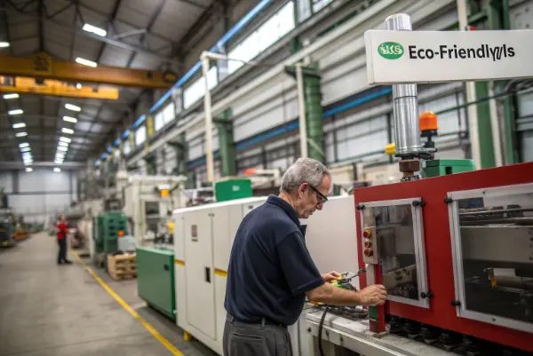
Quick answer: A mold fits a machine only when mechanical space, clamp and injection capacity, nozzle and locating interfaces, ejector stroke, utilities, hot runner, side actions, robot access and control signals all work together. Check actual dimensions and process demand before shipment or transfer, not just nominal tonnage.
Release Decision Matrix
| Interface | Required comparison | Failure if missed |
|---|---|---|
| Mechanical | Platen, tie-bar spacing, daylight, thickness and mounting | Mold cannot enter, clamp or open fully |
| Injection | Shot volume, plasticizing, pressure, rate, nozzle and sprue | Unstable fill, long recovery, leakage or material degradation |
| Ejection/actions | Stroke, pattern, force, threads, hydraulics and sensing | Part cannot release or action sequence becomes unsafe |
| Utilities/automation | Water, temperature, power, connectors, robot and I/O | Wrong thermal state, damaged equipment or manual workaround |
Approval Checklist
- Verify loading route, tie bars, platen, thickness, daylight and opening stroke.
- Confirm mounting, locating ring, mold support and clamp access.
- Calculate projected area, cavity-pressure basis and clamp reserve.
- Match shot volume, screw, pressure, rate, recovery and residence needs.
- Check nozzle, sprue, hot-runner zones and electrical connectors.
- Verify ejector, actions, sensors, sequence and safe home positions.
- Map coolant, heat, air, hydraulic and electrical utilities.
- Dry-run robot, mold protection and data handshakes before automation.
Check the Physical Mold Envelope
Compare mold width and height with tie-bar spacing and the actual loading route. Verify thickness against machine minimum and maximum, required opening stroke, daylight for the mold plus part removal, and any robot or operator access. Include hoses, junction boxes, cylinders and lifting hardware that extend beyond the mold plates.
Confirm platen hole pattern, slots, clamp access, locating ring and mold support. A large or offset mold may need additional support even when it is within nominal platen dimensions.
Match Clamp Demand to Projected Area
Calculate projected area for parts and runners at the parting plane and use a justified cavity-pressure basis. Check clamp-force reserve without automatically selecting the largest press. Too little force risks flash and damage; an oversized machine can create shot-utilization, control and commercial disadvantages.
Review mold stiffness, support pillars, interlocks and expected pressure distribution. Clamp tonnage cannot compensate for weak support or poor fitting.
Match the Injection Unit
Compare total shot mass and volume, cushion, screw diameter, plasticizing rate, recovery time, injection pressure and injection rate with the resin and cycle. Keep shot utilization in a range that supports controllable residence and dosing. High-temperature or shear-sensitive materials may impose tighter boundaries.
Verify nozzle radius, orifice, reach, shutoff design and sprue-bushing interface. For hot runners, check manifold voltage, heater and thermocouple count, connector standards and controller zoning before connection.
Verify Ejector and Side-Action Interfaces
Check ejector pattern, rod diameter, thread, stroke, force and return confirmation. Confirm whether the machine ejector pushes the mold plate directly or through adapters. Define safe home positions and interlocks.
List hydraulic, pneumatic and unscrewing actions with pressure, flow, connectors, timing and sensors. The control sequence should prevent clamping on an action that is not home and prevent ejection before all required motion is complete.
Standardize Utilities and Connections
Document cooling and heating circuits, media, temperature, flow, pressure, hose size and connection type. Separate mold circuits from hot-runner or valve-gate air. Label every connection and verify the receiving plant can provide the required controllers, pumps, chillers and safety rating.
Check electrical supply, grounding, junction-box location and cable protection. Imported tools often need adapter planning for regional connector and utility standards; improvized fittings at startup create delay and error risk.
Dry-Run Automation and Data Handshakes
Review robot reach, end-of-arm tooling, clearance, part orientation, sprue handling and reject logic. Define mold-protection inputs, action confirmations, cavity sensors and any quality signals sent to downstream equipment. Test the sequence slowly before automatic cycling.
Retain an interface sheet with drawings, photographs, pinouts and approved adapters. Repeat the checklist after a machine transfer, major mold repair or automation change. Compatibility is a controlled configuration, not a one-time assumption.
Illustrative Mold-Transfer Check
Illustrative engineering example—not a claimed CKMOLD customer result: A mold was quoted for a 350-ton press and is moved to another 350-ton machine. The clamp rating matches, but the receiving press has narrower tie bars, a different ejector thread and insufficient valve-gate control zones. An interface review catches these items before shipment and defines a support adapter, ejector coupling and controller plan.
Supporting Review Resources
Questions Before Approval
Is clamp tonnage enough to confirm mold-machine fit?
No. Physical envelope, shot and pressure, nozzle, ejector, utilities, actions, automation and controls also need confirmation.
Why can two machines with the same tonnage differ?
They can have different platen geometry, tie bars, screw sizes, pressure and rate, daylight, ejector, controls and utility interfaces.
What should be checked for an export mold?
Confirm receiving-machine drawings, regional utilities and connectors, controllers, mounting, documentation, spare adapters and test conditions before shipment.
When should the interface checklist be repeated?
Repeat it for mold transfers, machine changes, major repairs, action changes or new automation that alters the controlled configuration.
Apply the Machine-to-Mold Interface Checklist for Injection Molding review to your released design. Share the function, exact resin, annual volume, CTQs, cosmetic limits and launch timing through the CKMOLD project form. If CAD is relevant, send it directly to jerry@ckmold.com; the form does not require an upload.