
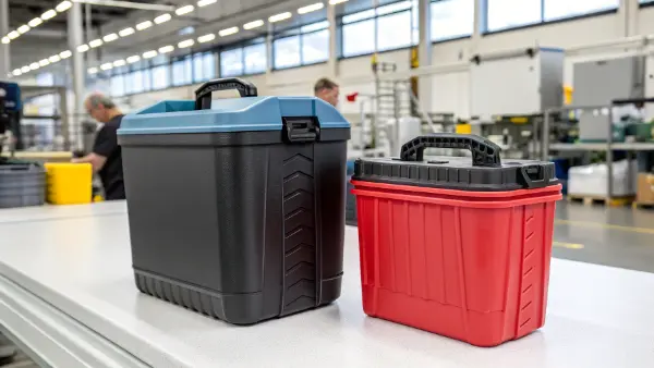
Two-component molding is worth considering when an integrated grip, seal or color feature removes a separate assembly step or provides a function that a single material cannot meet. The decision depends on the exact material grades, bond or retention design, tooling, production demand and acceptance tests. Appearance alone does not establish a cost or performance advantage.
Two-component (2K) injection molding combines two materials, or two colors of a compatible material, in one molded component. In a typical two-shot sequence, the first shot forms a substrate and the second adds the grip, seal or other feature. It can reduce separate assembly, but it does not automatically produce a leak-proof container, permanent adhesion or a shorter cycle.
Compare the proposed integrated design with a single-material part and a separately assembled seal or grip. Keep the functional requirements and accepted annual quantity the same in each comparison. The sections below identify what needs to be demonstrated before committing to a two-component tool.
How Does Two-Component Molding Make Containers Look Better?
Two colors, a contrasting texture or a soft-touch area can distinguish a container. Define the cosmetic boundary, color tolerance, surface texture and acceptable witness lines on the drawing so that appearance can be inspected consistently.
The process can combine contrasting colors and surface finishes in a molded component. A window, logo or grip still needs a moldable geometry, suitable material pairing and a defined shut-off between the shots. Review flash, sink, alignment and warpage at that boundary using representative samples.
A glossy rigid body with a contrasting soft grip is a possible design concept, not evidence of a sales increase. Validate grip feel, color, cleaning resistance and durability with the intended users and service conditions before describing a commercial or functional benefit.
The Power of Multi-Color and Texture
Molded-in color or texture may replace selected decorating operations, but a second material does not remove mandatory product labeling or all finishing. Match the texture and overmold coverage to the grip function, and approve physical color and finish samples.
Treat Electronic Inserts as a Separate Design Decision
Embedding an NFC tag is an insert-molding or assembly decision, not an automatic feature of two-component molding. It requires a suitable insert, positioning method and verification that molding and service conditions do not damage the electronics. Include its cost, inspection and effect on recycling separately.
| Design feature | Potential purpose | What to verify |
|---|---|---|
| Soft-touch grip | Improve handling | Grip under dry, wet and cleaning conditions; attachment durability |
| Two colors or finishes | Identify a feature or brand area | Color approval, boundary alignment, flash and surface defects |
| Electronic insert | Add a specified electronic function | Insert survival, position, read performance and end-of-life implications |
Specify an appearance acceptance sample and inspection conditions. A more complex mold is justified only when the added feature delivers an agreed benefit; it is not evidence that customers will pay more.
Can Two-Component Molding Improve Container Function?
For a sealing application, start with the leak path, contact pressure, mating tolerances, contents, temperature and opening cycles. Determine whether an integrated seal is preferable to a replaceable gasket. A bonded seal that cannot be replaced may create a different service-life trade-off.
A soft sealing edge or grip can be integrated with a rigid substrate, reducing the risk of a separately fitted part being omitted or misplaced. Sealing still depends on geometry, compression, material properties, tolerances and aging. Test the finished lid-and-container assembly; adhesion alone does not prove leak resistance.
For a container with a separately installed ring, compare assembly errors, cleaning access, seal replacement and end-of-life separation with the integrated design.
Building a Better Seal
The first shot forms the rigid lid or body; the next shot forms the sealing feature. Select grades intended to bond under the proposed process conditions, or design appropriate mechanical retention. Verify attachment and sealing separately after temperature exposure, cleaning and repeated use. A bond must not be described as permanent without a defined durability requirement and supporting test results.
Define Contact and Cleaning Requirements
For food-contact applications, review the exact resin grades, additives, colors and intended contact conditions for the target market. A generic PP or TPE designation does not establish suitability. Validate cleanability and material resistance to the specified washing process.
| Functional feature | Candidate design | Required verification |
|---|---|---|
| Sealing rim | Suitable elastomer on a rigid substrate | Leakage, compression set, aging and lid tolerances |
| Grip or anti-slip base | Grade selected for the contact surface | Friction under actual use conditions, wear and attachment |
| Reusable food-contact container | Specified grades and additives | Applicable contact documentation, cleaning and finished-part requirements |
Do not infer antimicrobial performance, food safety or leak resistance from the molding method. Any such claim needs evidence for the actual material and finished product under the stated conditions.
What Are the Best Material Choices for Two-Component Containers?
Poor adhesion can arise from an unsuitable material pairing, contamination, additives, processing conditions or inadequate retention geometry. Specify both grades and review the interface before selecting a tool concept.
A rigid substrate and an elastomer are one common combination, but the correct pair is application-specific. Check adhesion, shrinkage, substrate stiffness, service temperature, chemical exposure and any contact requirements. PP, ABS and PC are material families, not guarantees that every grade will bond or suit a food container.
Obtain the material supplier’s recommendation for the exact substrate, overmold grade and color/additive package. Avient's overmolding selection guidance lists different TPE products for different substrates; it does not treat all TPEs as interchangeable.
The Rule of Material Compatibility
Adhesion depends on the selected formulations and processing window; similar melting temperatures alone do not establish compatibility. Control surface cleanliness, time between shots and substrate support. Where justified, use mechanical interlocks to assist retention, as described in Avient's overmolding part-design guidance. Verify the resulting bond under the intended loads and aging conditions.
Candidate Material Pairings
The pairings below are starting points for a material review. Each requires grade-specific validation for the intended product and process.
| Substrate | Candidate second material | Selection boundary |
|---|---|---|
| PP | A TPE grade designed for PP overmolding | Confirm the exact grade, adhesion and contact conditions |
| ABS | An elastomer grade specified for ABS | Check thermal exposure, adhesion and service chemicals |
| A suitable high-temperature substrate | A compatible silicone grade | Validate cure conditions, substrate stability and adhesion or retention |
Silicone overmolding needs particular care because the cure conditions can deform an unsuitable thermoplastic substrate; see Avient's TPE and silicone comparison. Use the plastic-material selection overview to define the service requirements, then confirm the specific grades.
How Does This Process Cut Costs and Boost Efficiency?
Assembly labor may be a cost driver, but compare it with the added tooling, machine, process-control and maintenance costs of two-shot production. Some integrated designs still require handling, trimming, inspection or downstream assembly.
Two-component molding can reduce separate handling and assembly. Its total cost depends on tool investment, machine rate, shot sequence, cycle time, cavity count, yield, material prices, maintenance and demand. High volume spreads fixed costs; it does not by itself prove that two-shot molding is cheaper.
Build the comparison from the current assembly operation: accepted output, labor time, component loss, inspection and rework. Use measured or quoted inputs and identify uncertainty.
Fewer Steps Mean More Profit
Count the operations that the proposed design actually removes. Include any remaining degating, inspection, cleaning, packaging and reject handling. Compare accepted parts per hour rather than the fastest isolated machine cycle.
Understanding the Practical Tradeoffs
Two-shot tooling must control the substrate position, transfer or indexing, second-shot cavity and interface. Establish machine compatibility and maintenance access at the DFM review. Tool complexity and launch risk belong in the business case.
| Cost factor | Separately made and assembled parts | Integrated two-component part |
|---|---|---|
| Tooling and equipment | Quote each tool, fixture and assembly station | Quote the tool concept, machine and handling requirements |
| Recurring cost | Material, molding, assembly, yield and inspection | Both materials, cycle, machine rate, yield and inspection |
| Quality risk | Missing, misplaced or poorly attached components | Interface defects, flash, warpage and bond or seal failures |
For each feasible route, compare total cost = fixed investment + accepted quantity × accepted-part cost. A break-even quantity exists only when the higher-investment route has a lower recurring cost. Test the launch and expected repeat-order volumes; there is no universal few-thousand or million-part cutoff.
What Process Options Exist for Two-Component Molding?
Choose the process from the part geometry, access to the second-shot surface, material behavior, machine capability and production demand. Review how the substrate will be supported and located during the second shot.
Two-shot systems may use rotary indexing or a core-back arrangement to create the second-shot cavity. Alternatively, a separately molded substrate can be loaded into an overmolding tool. Loading may be manual or automated. These options have different tooling, transfer, cooling and handling constraints; none is always the fastest or cheapest.
Request a proposed molding sequence, machine interface and cycle-time breakdown with the quotation. The supplier should explain how the first shot remains located, how the second cavity seals, and how the finished part is ejected.
The Rotary Platen Method
A rotary arrangement indexes the first-shot substrate to a second molding station. It can support efficient repeated production when the two shots and cooling requirements are balanced. Alignment, substrate retention, shut-offs and machine capacity remain design and validation requirements.
The Movable Core Method
In a core-back arrangement, a movable tool element retracts after the first shot to create space for the second material. The geometry must allow the movement and a reliable shut-off. Its cost and suitability depend on the particular design; it is not automatically a cheaper replacement for indexing.
| Process option | Potential fit | Main review points |
|---|---|---|
| Rotary indexing | Repeated production with accessible second-shot features | Machine interface, indexing accuracy, retention and cycle balance |
| Core-back | Geometry that permits a movable cavity boundary | Core travel, shut-off, venting and flow |
| Insert overmolding | A separately produced substrate | Loading, cleanliness, position, support and automation options |
Select the method after the material and geometry review. Approve the interface appearance and functional tests on samples from the intended process rather than choosing a machine arrangement as a quality guarantee.
Is Two-Component Molding Good for the Environment?
Environmental performance must be evaluated for the complete design and manufacturing route. A second material may remove an assembly operation, but it may also complicate sorting and recycling. Do not equate a single molding machine with lower total energy use.
Two-component molding is not inherently more recyclable or lower in carbon impact. Compare material mass, start-up waste, rejects, energy per accepted part, transport and the actual end-of-life route. Bonded materials require a recycling-compatibility assessment; belonging to a similar polymer family does not prove that a local collection or recycling system will accept the container.
Define the baseline and the claimed improvement before using environmental language in product marketing. Record the boundary of the comparison, the measured inputs and the market in which the end-of-life claim is intended to apply.
Measure Factory Waste
Measure runner and purge waste, start-up rejects, rejected substrate/overmold pairs and downstream scrap for both routes. A defective second shot can make both materials unusable. Assess energy per accepted part, including auxiliary equipment, rather than comparing only the number of machines.
Check Recycling Compatibility
Assess the complete package, including the grip, lid, pigments, labels, adhesives and electronic inserts. APR's PP packaging evaluation protocol provides a framework for testing compatibility with the PP recycling stream. A compatibility result and access to local collection are separate questions.
| Proposed improvement | Evidence needed | Limitation |
|---|---|---|
| Remove adhesive assembly | Equivalent functional and durability tests | Does not establish food-contact suitability |
| Reduce energy or waste | Comparable measured inputs per accepted part | Fewer machines do not prove a lower footprint |
| Improve recyclability | Package-level assessment for the intended recycling stream | Collection and acceptance vary by market |
If end-of-life separation or a single-material design is a priority, compare those options before integrating the grip permanently. State only the recycling outcomes supported for the actual package and intended market.
Conclusion
Choose two-component molding when the integrated feature has a clear purpose and the material pair, tool concept, economics and acceptance tests support it. For a container molding quotation, provide the CAD and drawing, both material grades or performance requirements, annual demand, contact and cleaning conditions, cosmetic boundaries, and bond or leak-test criteria.